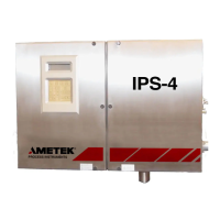
1-8 | IPS-4 Dual Bench (UV / IR) Analyzer
Electronics
The 512 or 1024 element channel detector is mounted on a board which
performs some signal conditioning. The signal passes to the MCU board
which contains the main analyzer processor. The analyzer internal and
external analog and digital inputs/outputs, along with relays, etc., are
handled by the Analog and Relay boards.
The main user interface consists of a keypad/display, also known as the
User Interface Panel. Other boards include the Customer Connection
board, a Display Interface board to run the display, and a Xenon Lamp
board. Smaller processors on some of the ancillary boards – all tied into
the main MCU – handle local tasks.
The main functions of the processors are to:
• Control the lamp and detector settings.
• Monitor and control temperatures in the Oven/Sample System Enclo-
sure (if required) and Optical Bench.
• Monitor sample system pressure.
• Monitor and control temperatures in the sample line.
• Monitor and control temperatures in the probe.
• Monitor alarm relays and other system health.
• Control the sample system including valves, etc.
• Calculate the fluid absorbances and concentrations.
For external communication, RS-232, RS-485, and Ethernet ports are avail-
able. Analog signals are also available to the customer through configu-
rable 0–20 mA or 4–20 mA outputs.

 Loading...


