23
SETUP "BASIC SETTINGS"
Par.
7. 4
Conrm access
or data change
Exit the function or
data change
Delete
selected
character
Scroll
(LEFT /
RIGHT)
Data
increase /
decrease
Scroll
(UP /
DOWN)
Enter
selected
character
4A GUIDED SETUP PROCEDURE FOR SELF-PROPELLED MACHINES
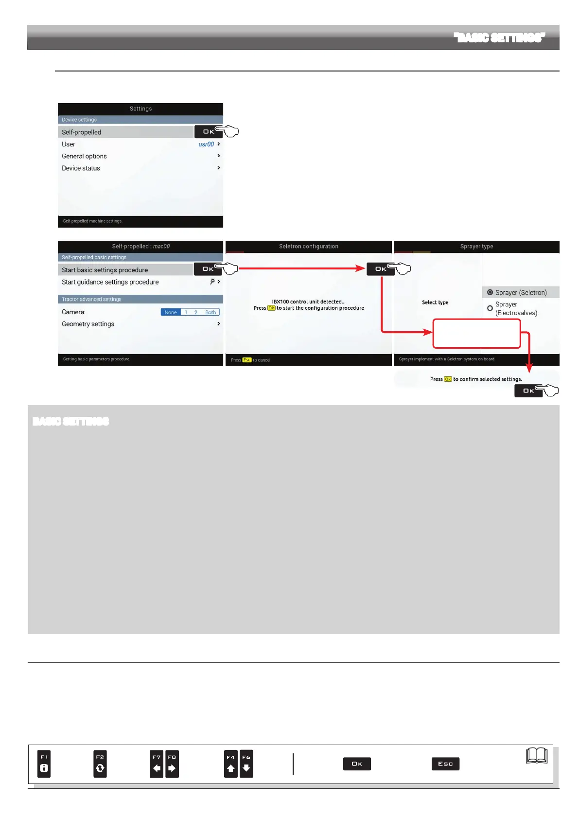
- From the "Home" page press F8.
- Select
Self-propelled (Fig. 48) and press OK.
Fig. 48
Start basic settings procedure (Fig. 49)
- Delta 80 guides you through the setup procedure: follow all suggested steps and select required
options.
OK: next step ESC: previous step.
- When message
Press Ok to confirm selected settings,
is displayed, setup is completed. Press OK.
- Now select
Start guidance settings procedure and go to guided setup procedure Fig. 52.
Fig. 49 Fig. 50
OK Next step
ESC Previous step
Fig. 51
BASIC SETTINGS
• IMPLEMENT TYPE
Sprayer (Seletron)
: system with Seletron valves.
Sprayer (Electrovalves): system with electric-activated valves - with gearmotor.
• MAIN VALVE
Main control valve installed on the control unit:
None
2 ways (drain valve)
3 ways (main valve)
• SPRAYING SPOT TYPE
Seletron type: single, twin or fourfold
• FLOWRATE REFERENCE SENSOR
Device used to calculate owrate:
Flowmeter
Pressure sensor: measured pressure is used to calculate application rate.
Both: within the working limits the computer uses the owmeter, otherwise it uses the pressure sensor, ONLY if properly congured.
• TERMINAL NOZZLES
None
"Buffer zone" nozzles
: use switch panel to select nozzle to be used at "Buffer zone", see par. 12.2.1 "Buffer Zone" function enabled on page 74.
• TANK LEVEL SOURCE
Device used to read tank level:
Manual: no device connected
Filling flowmeter
Tank level sensor
CONTINUES