Argo Service Manual Wheels, Axles & Chains
Ontario Drive & Gear Limited www.odg.com
PH.(519)- 662-2840 FAX (519)- 662-2421
WA-29
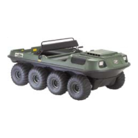
ii. Push the idler shaft into the inner bearing, and lift up and out at the bearing and
flange assembly on the opposite end of the shaft. Photo WA-60
WA-60
iii. For the right hand side idler shaft, you will need to pull the floating sprocket to-
wards you as far as the spline of the shaft will allow.
iv. With a retaining ring pliers pull the inboard retaining ring back and up against the
sprocket. Photo WA-61
v. Push the idler shaft into the inner bearing, and lift up and out at the bearing and
flange assembly on the opposite end of the shaft. Photo WA-62
iv. Move the idler shaft assembly to a clean work area and remove the bearings,
flanges, retaining ring, and the floating double sprocket.
WA-59
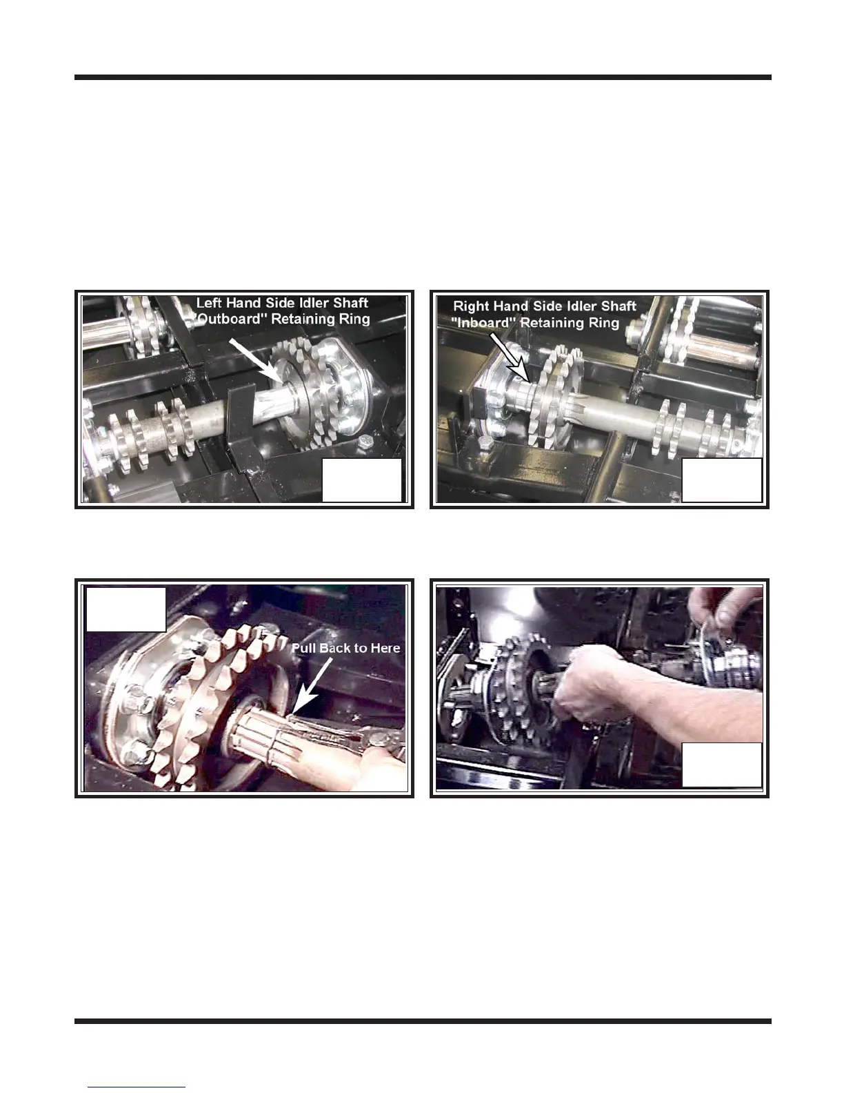
On vehicles manufactured from S/N CB16970, RB17033, BF11543 and C Vehi-
cles:
Argos manufactured from the above serial numbers utilize a retaining ring on each idler
axle shaft. The left hand side idler axle shaft has 1 retaining ring which is “outboard” to
the floating double sprocket. The right hand side idler axle shaft has a retaining ring
which is “inboard” to the floating double sprocket. Photo WA-57 & 58
i For the left side idler shaft, you will need to pull the retaining ring away from the
floating sprocket, towards the end of the spline. Photo WA-59
WA-57 WA-58