Wheels, Axles & Chains Argo Service Manual
Ontario Drive & Gear Limited www.odg.com
PH.(519)- 662-2840 FAX (519)- 662-2421
WA-34
On vehicles manufactured prior to S/N CB16970, RB17033 and BF11543:
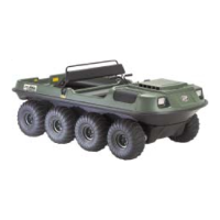
i. Assemble the floating sprocket to the idler shaft with the set screw side facing out-
wards (towards the outer bearing). Photo WA-70
1. Begin by applying anti-seize compound along the spline of the idler shaft, as well as
at both ends where inner and outer bearings are installed.
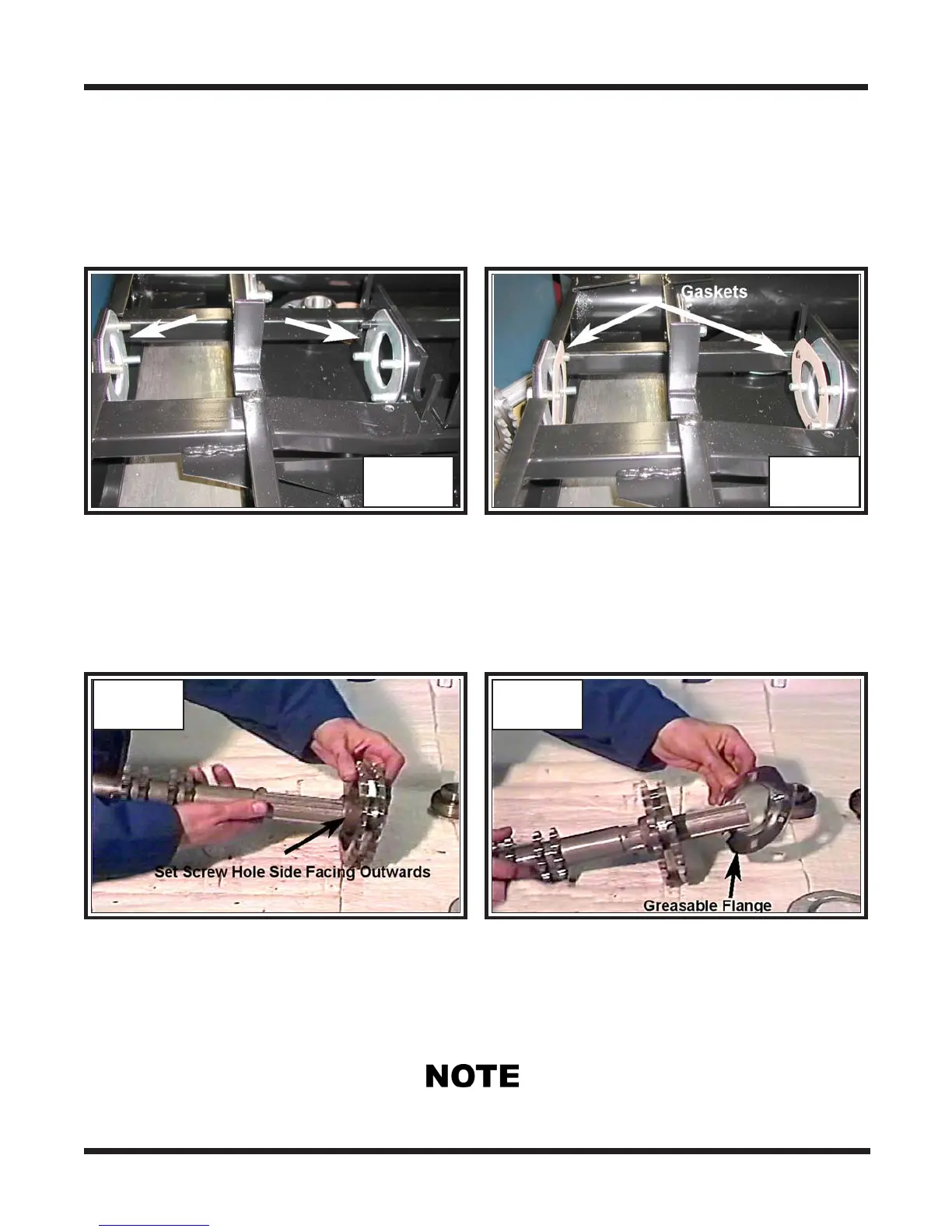
2. Assemble a flange to both inner and outer bearing mount studs on the lower frame.
Photo WA-68
3. Place a gasket to each of the previouly installed flanges. Photo WA-69
WA-68 WA-69
WA-70 WA-71
Take note of the machined indents on this end of the shaft. Bearing set screws are aligned
and secured at these locations in a later assembly operation.
ii. Slip the greasable flange to the same side as the sprocket. Photo WA-71
iii. Slip the inner bearing on to the shaft with the set screws and collar facing towards
the sprocket. Photo WA-72
iv. Install a greasable flange and the outer bearing to the opposite side of the shaft, once
again facing the collar and set screws of the bearing inwards. Photo WA-73