Embedded Trace Macrocell
ARM DDI 0500D Copyright © 2013-2014 ARM. All rights reserved. 13-49
ID021414 Non-Confidential
Usage constraints There are no usage constraints.
Configurations Available in all configurations.
Attributes See the register summary in Table 13-3 on page 13-10.
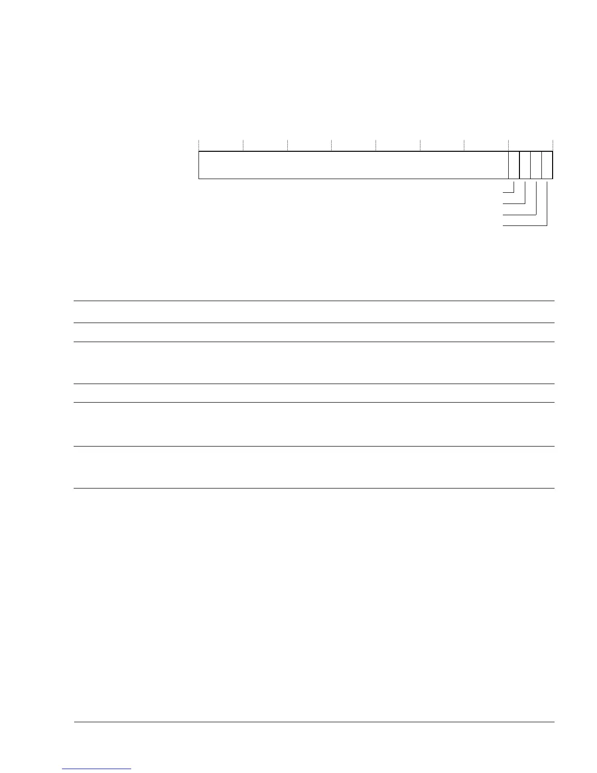
Figure 13-43 shows the TRCOSLSR bit assignments.
Figure 13-43 TRCOSLSR bit assignments
Table 13-44 shows the TRCOSLSR bit assignments.
The TRCOSLSR can be accessed through the internal memory-mapped interface and the
external debug interface, offset
0x304
.
13.8.42 Power Down Control Register
The TRCPDCR characteristics are:
Purpose Request to the system power controller to keep the ETM trace unit
powered up.
Usage constraints There are no usage constraints.
Configurations Available in all configurations.
Attributes See the register summary in Table 13-3 on page 13-10.
Figure 13-44 on page 13-50 shows the TRCPDCR bit assignments.
Table 13-44 TRCOSLSR bit assignments
Bits Name Function
[31:4] - TRCRSCTLR
N
[3] OSLM[1] OS Lock model [1] bit. This bit is combined with OSLM[0] to form a two-bit field that indicates the OS Lock
model is implemented.
The value of this field is always 0b10, indicating that the OS Lock is implemented.
[2] nTT This bit is RAZ, that indicates that software must perform a 32-bit write to update the TRCOSLAR.
[1] OSLK OS Lock status bit:
0
OS Lock is unlocked.
1
OS Lock is locked.
[0] OSLM[0] OS Lock model [0] bit. This bit is combined with OSLM[1] to form a two-bit field that indicates the OS Lock
model is implemented.
The value of this field is always 0b10, indicating that the OS Lock is implemented.