110-TYPE HARDWARE
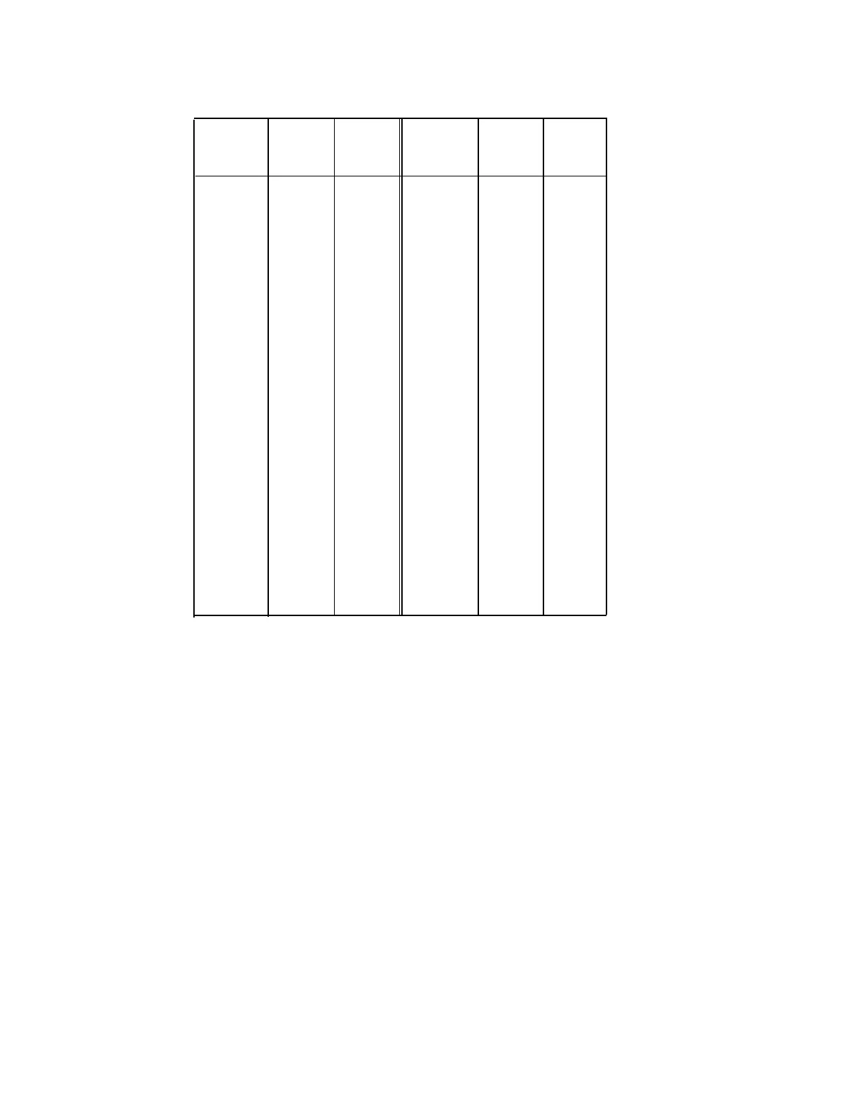
TABLE 3-C. WP-90929, List 3, Cable Assembly Wiring
Conn. 0
Pin
No.
Cable
No. 1
Cable
No. 2
Conn. 0
Pin
No.
Cable
No. 1
Cable
No. 2
26
27
28
29
30
31
32
33
34
35
36
37
38
39
40
41
42
43
44
45
46
47
48
49
50
W-BL
W-O
W-G
W-BR
W-S
R-BL
R-O
R-G
R-BR
R-S
BK-BL
BK-O
-
-
-
-
-
-
-
-
-
-
-
-
V-S
-
-
-
-
-
-
-
-
-
-
-
-
W-BL
W-O
W-G
W-BR
W-S
R-BL
R-O
R-G
R-BR
R-S
BK-BL
BK-O
-
1
2
3
4
5
6
7
8
9
10
11
12
13
14
15
16
17
18
19
20
21
22
23
24
25
BL-W
O-W
G-W
BR-W
S-W
BL-R
O-R
G-R
BR-R
S-R
BL-BK
O-BK
-
-
-
-
-
-
-
-
-
-
-
-
S-V
-
-
-
-
-
-
-
-
-
-
-
-
BL-W
O-W
G-W
BR-W
S-W
BL-R
O-R
G-R
BR-R
S-R
BL-BK
O-BK
-
16-PORT ANALOG LINE BOARD ADAPTER CABLE
The 16-port analog line circuit pack (TN746) has an output of sixteen 1-pair circuits that
appear on a 25-pair connector at the switch. The 16-port analog line adapater cable
(Figure 3-14) separates the 1-pair circuits into 3-pair circuits that appear on two 25-pair
connectors at one end of the cable.
The adapter cable is 8 feet (2.4 m) long and can be ordered with the TN746 circuit pack. The
adapter cable is apparatus-coded as an adapter and can also be ordered below. This cable
should only be used with 110P-type hardware. Punch-down cross-connections using 110A-
type hardware allows direct access of the 16 ports via a single 25-pair cable. See Table 3-K
for lead assignments.
16-PORT ANALOG LINE
ADAPTER CABLE ORDERING INFORMATION
Description
Comcode
853B Adapter
104 305 834
3-27
 Loading...