66-TYPE HARDWARE
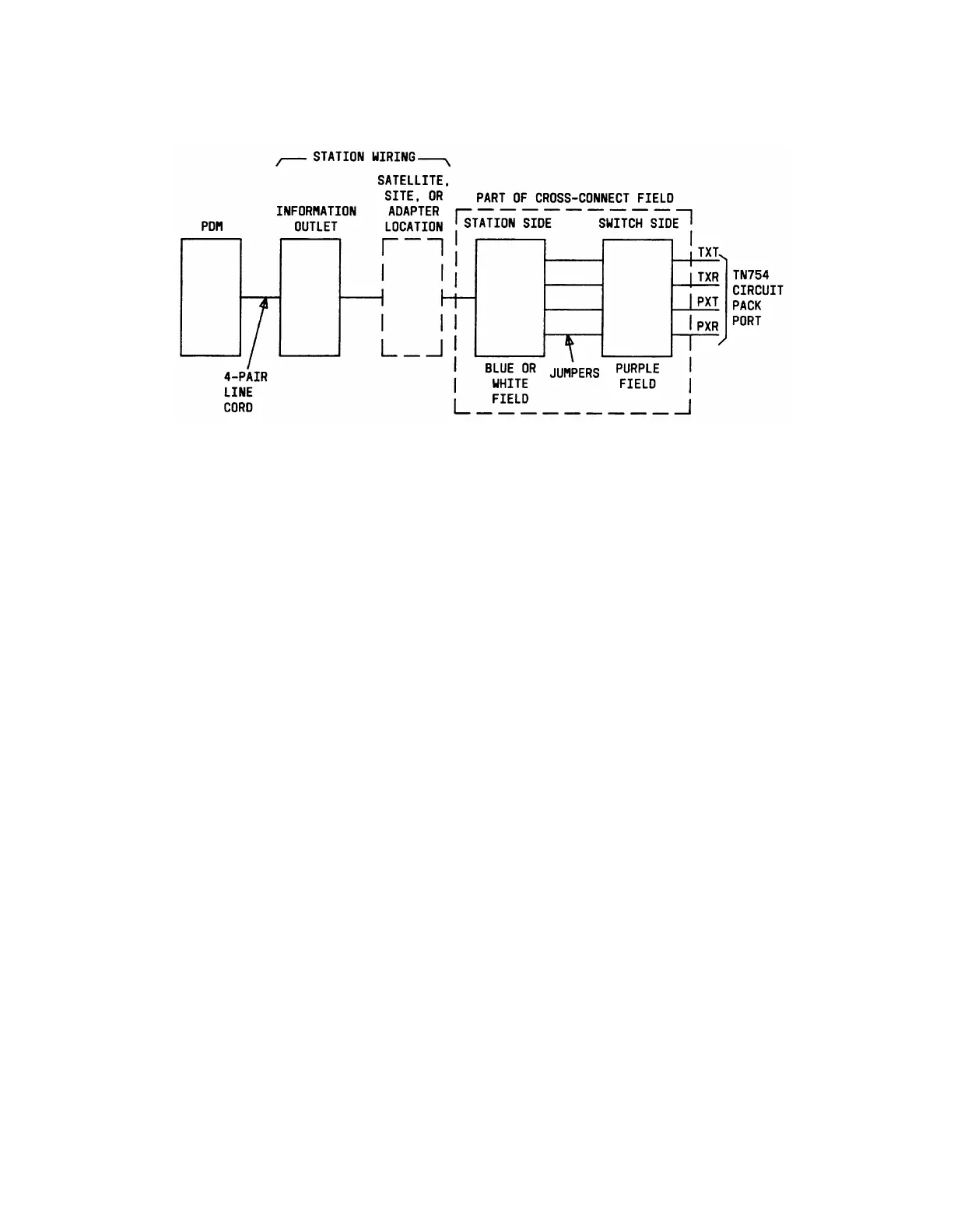
Figure 4-97. Connections for Individual PDMs
Installing Applications Processor Interface—System 75
Requirements
The interface between System 75 and the Applications Processor/Adjunct or Applications
Processor/Terminal is through processor data modules (PDMs). Applications Processor
alarms are connected through the trunk/auxiliary field to the System 75. Applications
Processor Terminals can also reconnected through the System 75 cross-connect field to the
Applications Processor.
●
System 75 Version 1 includes Interface 1 (TN716), Interface 2 (TN720), and Interface
3 (TN719) as the required control circuit packs.
●
System 75 Version 2 or 3 includes Interface 1 (TN716), Interface 2 (TN738), and
Interface 3 (TN719) as the required control circuit packs.
The installation for the Applications Processor Interface from the System 75 switch is
covered under the section for installing PDMs (see Figures 4-96 and 4-97).
Information for connecting the PDMs to the Applications Processor and setting the PDM
option switches is contained in Applications Processor 16—Installation, Administration, and
Acceptance Test—Service Manual, 585-201-102.
The connections for the Applications Processor Alarms are shown in Figure 4-98.
Installation of Applications Processor Alarms Connection to Alarms
1.
2.
3.
Run and connect A25B cable from REMOTE ALARM connector on rear of
Applications Processor to connecting block in the Trunk/Auxiliary Field to be used
for the Applications Processor alarms (see Figure 4-98).
At Trunk/Auxiliary Field, connect jumpers from seventh pair on the connecting
block in the yellow field for the Applications Processor to ALARM MONITORS 1M
terminals (see Figure 4-98). Designate seventh pair as MAJ 1.
Connect jumpers from ninth pair on the connecting block in the yellow field for the
Applications Processor to ALARM MONITORS 1m terminals (see Figure 4-98).
Designate ninth pair as MIN 1.
4-148
 Loading...