110-TYPE HARDWARE
Installing Coupled Bonding Conductor Grounding
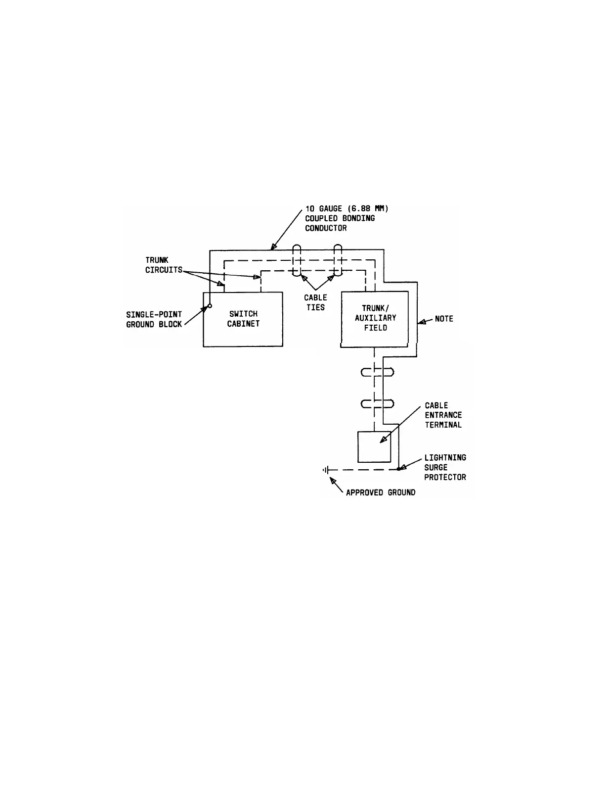
A coupled bonding conductor must be tie-wrapped to all trunk cables. The coupled bonding
conductor connects to the cabinet single-point ground block and runs all the way to the
approved ground located nearest the telephone company-owned protector block at the
building cable entrance facility (see Figure 3-70).
Note: Approved ground is defined in the AT&T System 75—System Description (555-
200-200) or AT&T System 75 XE—System Description (555-201-200)..
NOTE:
1.
2.
3.
4.
AT THIS POINT, THE ORDER
OF PREFERENCE FOR THE
COUPLED BONDING CONDUCTOR
IS AS FOLLOWS:
CONTINUOUS METALLIC CABLE SHEATH
10 GAUGE (6.88 MM) STRANDED WIRE
(TIE-WRAPPED TO CABLES)
SIX GOOD UNUSED CABLE PAIRS.
A COMBINATION OF THE ABOVE.
Figure 3-70. Coupled Bonding Conductor Grounding Installation
Installing Cables Between Switch Cabinet and the Cross-Connect Field
Before starting the following procedure, refer to Routing Cables From Switch Cabinet
to Cross-Connect Field guidelines. Also, all purple labels should have been previously
installed on the 110 terminal blocks as described under the heading Labeling the Cross-
Connect Field.
1.
Install self-stick port labels on the back of the cable connectors for the first switch
cable.
Note: Labels should not be obscured by the switch cabinet 25-pair connector
retainers.
3-94