110-TYPE HARDWARE
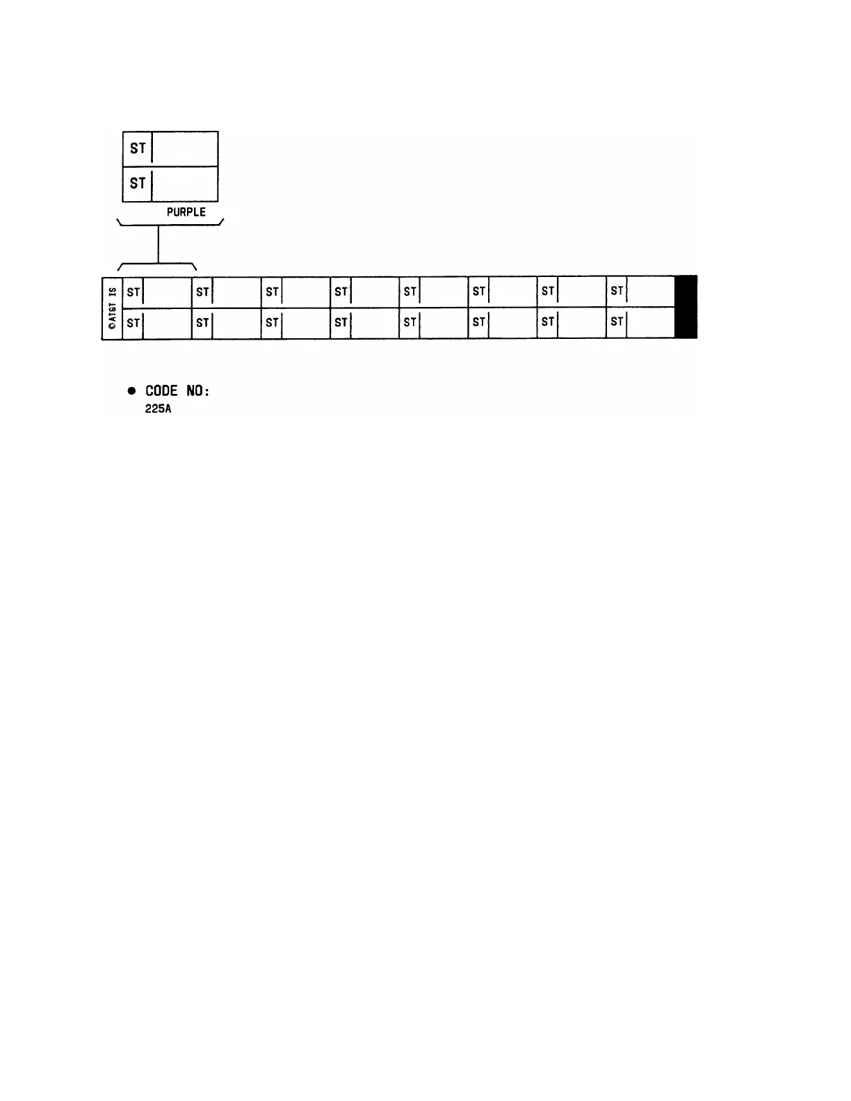
Figure 3-55. Dual-Purpose Emergency Transfer Station Labels
Label Code 225A—Purple Labels (103 970 059)
The label code for the port labels is 225A which contains the following:
●
45 purple labels (see Figure 3-50) that identify 3-pair port circuits from the switch.
The labels are numbered for the carriers at the switch A through E and each carrier
has slots numbered 1 to 20, except carrier A which is only 1 to 10. Each label
identifies 16 3-pair circuits.
●
10 unnumbered purple labels (see Figure 3-50) that identify 3-pair port circuits from
the switch. Each label identifies 16 3-pair circuits.
●
3 purple labels that identify 3-pair system trunk port circuits from the switch when
WP-90929, List 1 concentrator cables are used.
●
3 purple labels that identify 3-pair system tie trunk port circuits from the switch
when WP-90929, List 3 concentrator cables are used.
●
5 purple labels to identify connections to dual-purpose emergency transfer stations
(see Figure 3-55).
Installing the Sneak Fuse Panels
Install the sneak fuse panels as near as possible to the network interface. The sneak fuse
panel has two mounting screw slots. To install the panel, proceed as follows:
1.
2.
3.
4.
Hold the panel against the mounting surface and mark the upper right and lower
left mounting screw locations and remove panel.
Drill pilot holes at the marked locations, and partially install the screws.
Slide the panel onto the mounting screws and tighten.
Repeat the procedure for each additional sneak fuse panel.
3-77