110-TYPE HARDWARE
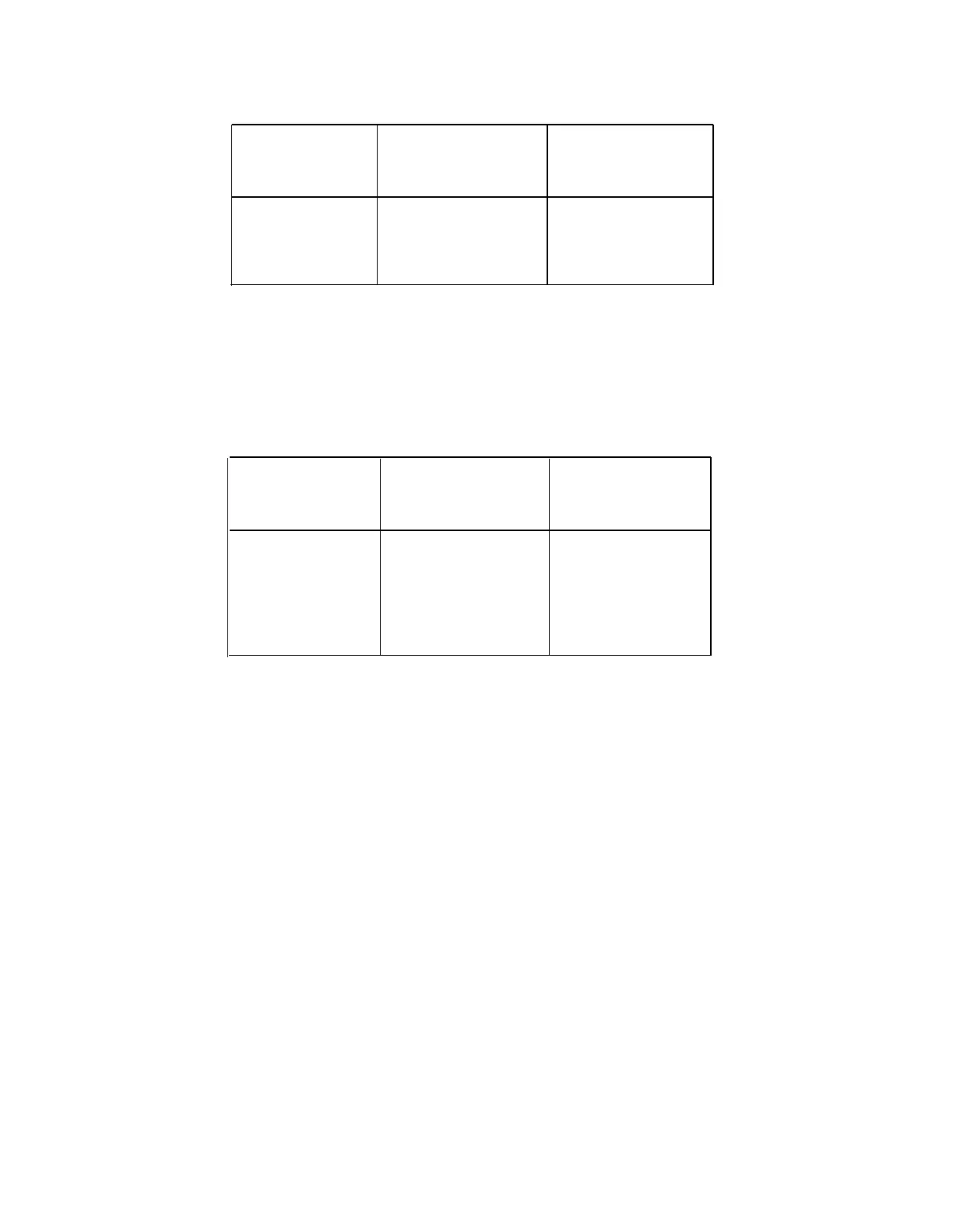
TABLE 3-G. Distribution Field—300-Pair 110P-Type Terminal Blocks
3-Pair Port Field
4-Pair Station Field 3-Pair Station Field
(Purple)
(Blue)
(Blue or White)
110PC1-300CT
110PB1-300CT 110PC1-300CT
110PB1-300FT 110PC1-300FT
The recommended 900-pair 110P-type terminal block for the purple field is the 110PC1-900CB
because the connectors exit the terminal block at the bottom which allows for easy cable
routing to the floor and the recommended use of cable slack managers with system. The
110PC1-900CT Terminal Block which has connectors that exit the top of the terminal block
can be used for the purple field if cable routing from the top is desirable. The types of
terminal blocks that can be used for the Distribution Field are shown in Table 3-H.
TABLE 3-H. Distribution Field—900-Pair 110P-Type Terminal Blocks
3-Pair Port Field
4-Pair Station Field
3-Pair Station Field
(Purple)
(Blue) (Blue or White)
110PC1-900CB 110PB1-900CB 110PC1-900CB
110PC1-900CT
110PB1-900CT
110PC1-900CT
110PB1-900FT 110PC1-900FT
Typical System Equipment Room Floor Plans
General
The equipment room floor plan must be provided by the Field Services Organization (FSO)
for firm quote price lists. For all other quotes, the equipment room floor plans must be
provided by the Premises Services Consultant (PSC). Factors that influence the design are
as follows:
●
Size and layout of the equipment room
●
Number of equipment cabinets
● AC outlet locations
● Size of the system.
Typical Floor Plans
Figure 3-25 shows a typical cross-connect field installation using 110A-type terminal blocks.
Figure 3-26 shows a typical cross-connect field installation using 300-pair 110P-type terminal
blocks and Figure 3-27 shows a typical cross-connect field using 900-pair 110P-type terminal
blocks. The cross-connect field is located directly behind the switch cabinet. This is the
preferred cross-connect field location.
Figure 3-28 is a typical floor plan for a 5-carrier System 75 cabinet or a 3- or 4-cabinet
System 75 XE. The maximum capacity for a 5-carrier cabinet is 800 stations.
3-40
 Loading...