66-TYPE HARDWARE
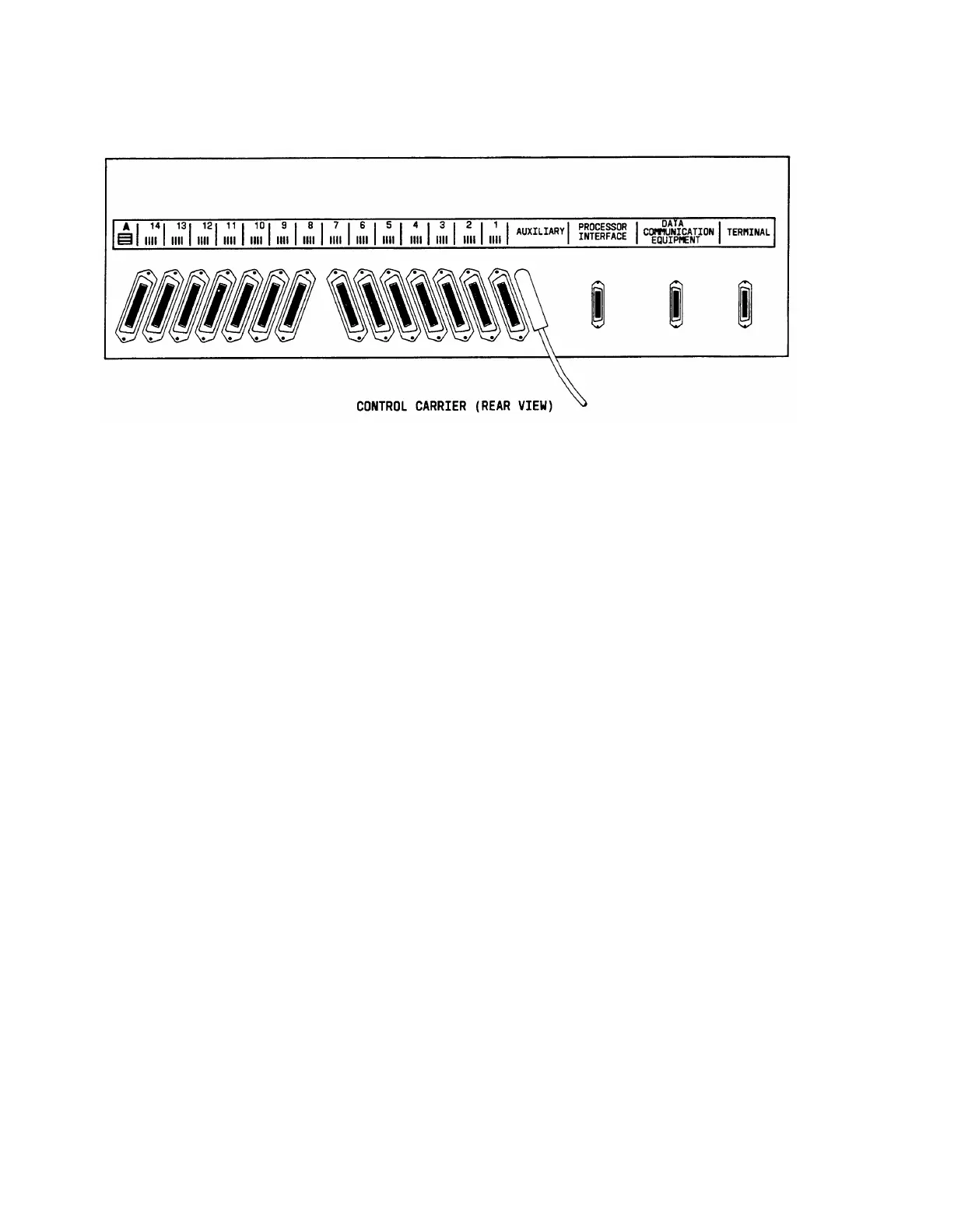
Figure 4-28. Control Carrier Outputs (AUXILIARY Connector)—System 75 XE
Installing Trunk Cables Between Network Interface, Sneak Fuse Panel, and System
Cabinet
The trunk pairs installed by the local telephone company will appear in the green field with
up to 24 pairs on each 66-type connecting block for the 1-pair central office trunks. The tie
trunks will appear in the green field with up to eight 3-pair trunks on each 66-type
connecting block. WP-90929, Lists 2 and 4 concentrator cables are used between the 66-
connecting block in the purple field and the switch cabinet. jumper wires between the green
and purple fields can be used in order to establish the correct 3-pair modularity for both the
1-pair and 3-pair trunks. Table 4-G shows switch port appearances at the cross-connect
field, and Figures 4-29, 4-30, and 4-31 show the carrier connectors located on the rear of the
switch cabinet that are connected to the purple field.
4-51
 Loading...