66-TYPE HARDWARE
Connecting Trunk Pairs to the Switch Cabinet Using Jumper Wires To Establish 3-Pair Modularity
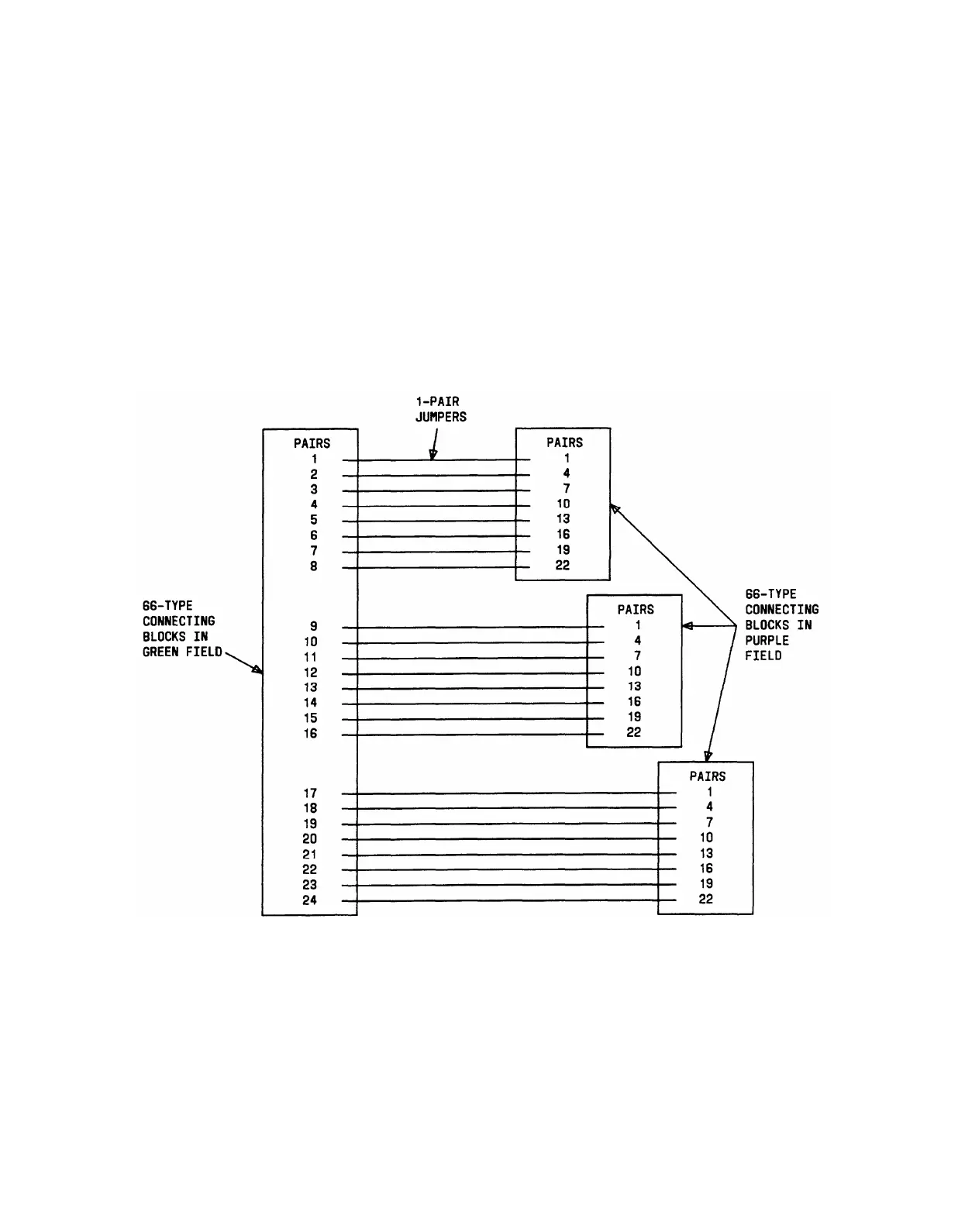
Figure 3-33 and 3-34 show trunk pairs connected to the switch cabinet using jumper wires to
establish 3-pair modularity. To connect the trunk pairs to the purple field, proceed as
follows:
1.
2.
3.
Connect B25A cables between the network interface and the sneak fuse panels.
Connect B25A cables from the sneak fuse panels to the 66-type connecting blocks in
the green field.
Connect 1-pair patch cords or jumper wires from each green 66-type connecting
block to the purple and yellow 66-type connecting blocks as shown by the example
in Figure 3-33 for 1-pair central office trunks or by the example in Figure 3-34 for
3-pair tie trunks.
Figure 4-33. Example of Establishing 3-Pair Modularity for Trunk Pairs Used
for 1-Pair Trunk Circuits; DID, Loop Start, Ground Start
4-56