110-TYPE HARDWARE
Voice Terminal Installation
12.
13.
Connect voice terminals to the information outlets.
Install patch cords or jumper wires between the switch side and the station side of
the Station Distribution Field.
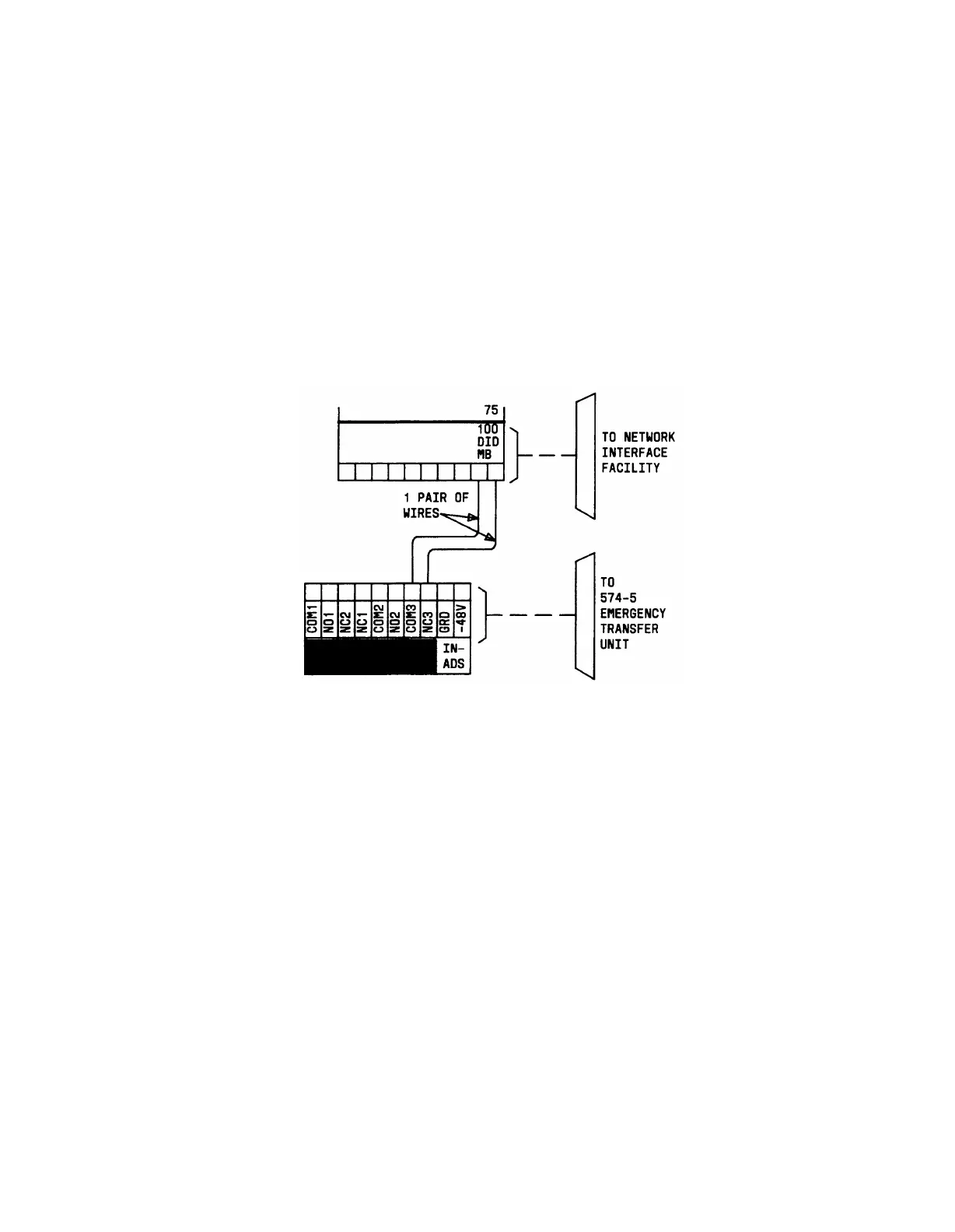
Installation—Optional DID Make-Busy Trunk
1.
2.
Run and connect jumper from one DID make-busy lead to COM3 terminal on the
yellow emergency transfer row (see Figure 3-106).
Run and connect jumper from the other DID make-busy circuit lead to NC3
terminal (first appearance) on the yellow emergency transfer row.
Figure 3-106. Connections at Trunk/Auxiliary Field for Optional DID Make-
Busy Trunk—574-5 Power Transfer Unit
Z1A Power Failure Transfer Unit
Figure 3-107 shows wiring required at the Trunk/Auxiliary Field for a voice terminal used
only for emergency transfer. Figure 3-108 shows wiring required at the Trunk/Auxiliary
Field for a voice terminal used for emergency transfer as well as a normal extension.
If a Z1A Emergency Transfer Unit is used with central office trunks that require ground
start, a ground start switch must be installed on each emergency transfer terminal. System
ground is provided on the twenty-fifth pair of leads on each purple row associated with a
switch cable when a cable is installed. System ground is connected to the third pair of the
3-pair terminal appearance. This pair becomes the second pair at the information outlet. A
ground start switch is mounted on the side of the terminals and is wired to ground and to
the ring lead inside the terminal.
3-144
 Loading...