66-TYPE HARDWARE
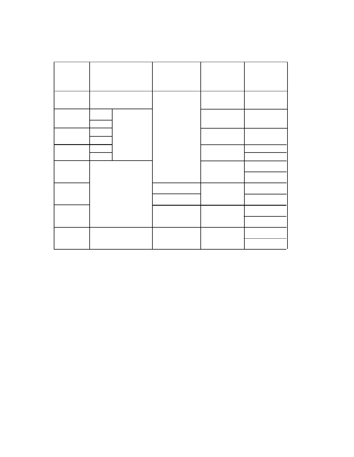
TABLE 4-H. Auxiliary Lead Appearances at 66-Type Cross-Connect Field
(Contd)
66 System 75 System 75 XE Z1A
574-5
Connecting
Auxiliary
Auxiliary
Emergency Emergency
Block
Connector
Connector Transfer Unit
Transfer Unit
Terminals
Outputs
Outputs
Outputs
Outputs
35
Not Connected
TK
36
TK
37
GND
38
-48
LC
LC
39
GND ACC Power Not Connected
40
-48
ST
ST
41
GND
TC
C0M1
42
-48
N01
43
NC2
TK
44
NC1
45
Ext Alarm A
C0M2
Not Connected
LC
46
Ext Alarm B
N02
47
C0M3
Not Connected
ST
48 NC3
49
GRD
INADS INADS
50
PWR
-48V
Installing the Sneak Fuse Panels
Install the sneak fuse panels as near as possible to the network interface. The sneak fuse
panel has two mounting screw slots. To install the panel, proceed as follows:
1.
2.
3.
4.
Hold the panel against the mounting surface and mark the upper right and lower
left mounting screw locations and remove panel.
Drill pilot holes at the marked locations, and partially install the screws.
Slide the panel onto the mounting screws and tighten.
Repeat the procedure for each additional sneak fuse panel.
4-41
 Loading...