66-TYPE HARDWARE
Connecting Trunk Pairs to the Switch Cabinet Using Concentrator Cables
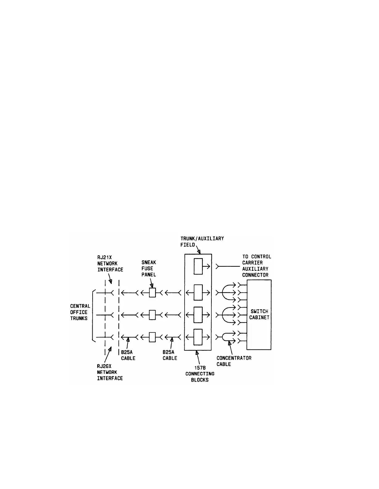
Figure 3-32 shows trunk pairs connected to the switch cabinet using concentrator cables. To
install the cables, proceed as follows:
1.
2.
3.
4.
5.
6.
7.
Connect B25A cables between the network interface and the sneak fuse panels.
Connect B25A cables from the sneak fuse panels to the 66-type connecting blocks in
the green field.
Install bridging clips on the 66-type connecting block (see Note).
Note: The left half of the 66-type connecting block will be labeled as part of
the green cross-connect field and the right half of the connecting block will be
labeled as part of the purple cross-connect field.
Connect the single-fingered end of the concentrator cables to the 66-type
connecting block.
Connect the 3-fingered end and 2-fingered ends of the concentrator cables to the
appropriate carrier slots. Equipped carrier slots are identified on the Customer
Service Order. It is helpful to mark the nomenclature strips above the carriers at
rear of cabinet to identify the equipped slots.
Label connectors on both ends of the cable that connect to the switch cabinet.
Dress cables down sides of cabinet and store excess cable slack in the cable slack
manager as described previously.
Figure 4-32. Connecting Trunk Pairs Used for 1-Pair Trunk Circuits; DID, Loop
Start, Ground Start Using Concentrator Cables
4-55