110-TYPE HARDWARE
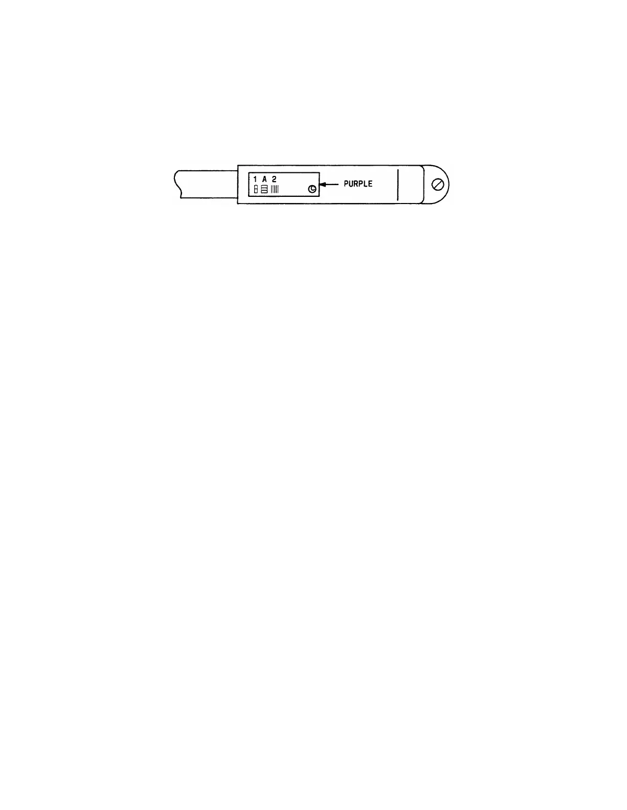
Figure 3-57 shows the proper label installation on a 25-pair cable connector (see Note).
Note: The label should be installed near the rear of the connector as shown so that it
will not be obscured by any of the switch cabinet connector retainers. It can also be
installed on the skin of the cable near the connector.
Figure 3-57. Self-Stick Label Installation on 25-Pair Cable Connector
Routing Cable Guidelines
The following guidelines should be followed when installing the equipment room cabling.
Following these guidelines will make optimum use of the cable slack managers and make
future cabling additions and changes easier.
General
Figure 3-58 shows cable routing through the cable slack manager for a 1-cabinet installation
using connectorized bottom terminal blocks. Figure 3-59 shows cable routing through the
cable slack manager using connectorized top terminal blocks. Cables route through the cable
slack manager in either the cabinet or wall troughs or when needed through the two center
troughs.
Port cables should use the cabinet trough for the parallel runs. The station cables should
use the wall trough. The center troughs are used after the cabinet and wall troughs are
filled.
Figure 3-60 shows typical cable routing from the switch cabinet to the cross-connect field
using connectorized bottom terminal blocks. Figure 3-61 shows cable routing from the
switch cabinet to the cross-connect field using connectorized top terminal blocks.
3-79
 Loading...