13 Draught Control
Mk8 MM Manual Page | 239
13 DRAUGHT CONTROL
13.1 Overview of Draught Control
Draught control is used to manage the excess draught from stacks, in both fire-tube and water-tube
applications, so heat transfer from the hot gases to the boiler tubes can be optimised. Both heat transfer rate
and combustion rate depend on the motion of the flue gases; any changes in boiler pressure can affect the
amount of combustion air entering the burner, possibly resulting in unburnt fuel. An excess of unburnt fuel
can lead to unsteady combustion with dangerous consequences. A tall stack is susceptible to a changing
pressure which is caused be stack temperature and wind velocity. The main benefits of maintain stack
pressure through draught control include:
• Improves heat transfer
• Improves combustion efficiency
• Reduces room heat loss
• Improves flame stability while reducing chance of pilot light failure
• Improves flame retention
• Reduce soot accumulation
The Autoflame draught control stores the pressure conditions at the commissioning stage and modulates
with the firing curve to maintain this, irrespective of changing firing rate and stack conditions. Normally there
is a vertical main stack which has a horizontal cross connection from the boiler flue gas outlet; this is then
connected into the main stack.
The boiler only works at optimum efficiency when all the conditions that affect its operation are held at good
commissioned values. Therefore, under the new arrangement, a butterfly valve driven by a positioning
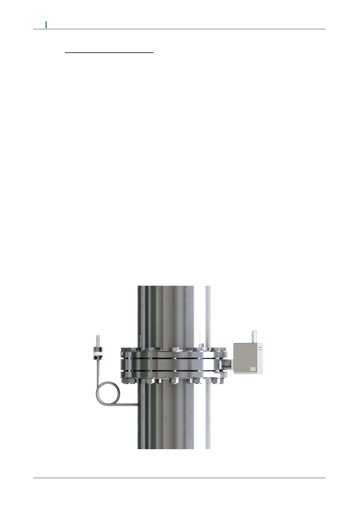
motor, is placed in the horizontal back flue typically two or three metres from the boiler. A differential
pressure sensor is then inserted into the flue that is between the boiler outlet and the butterfly valve. As
stack energy alters, the suction or pressure would vary at this point. It can be seen that by measuring the
pressure of the draught at the position of the damper could be adjusted to bring the pressure or suction back
to its commissioned value, the complete system would then be operating at optimum efficiency again.
Figure 13.1.i Stack with Draught Control

 Loading...

