10 Water Level Control
Mk8 MM Manual Page | 180
10.5.5 Configuration
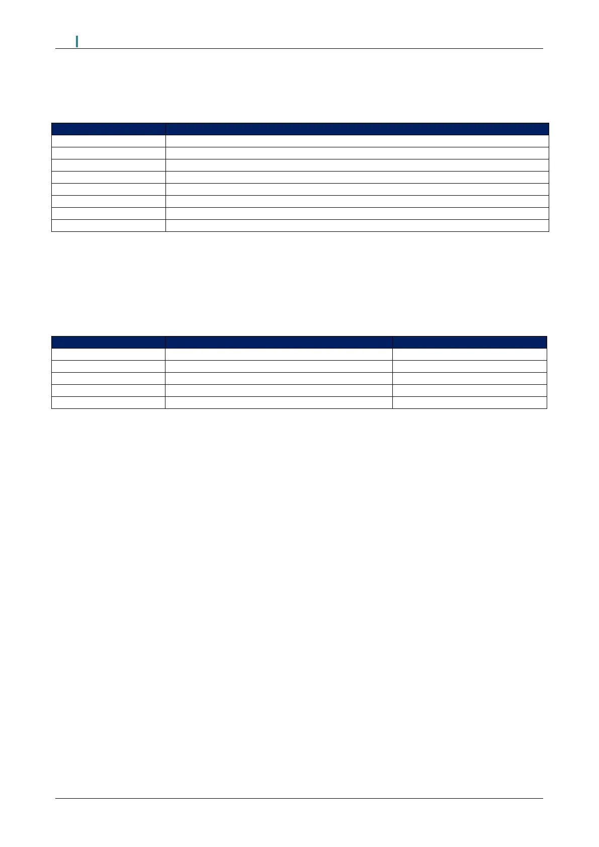
The table below shows the terminals allocated on the MM for the capacitance probes.
+9V supply to capacitance probe 1
0V supply to capacitance probe 1
Digital communications connections from capacitance probe 1
Digital communications connections from capacitance probe 1
+9V supply to capacitance probe 2
0V supply to capacitance probe 2
Digital communications connections from capacitance probe 2
Digital communications connections from capacitance probe 2
When wiring the capacitance probes, the screen is connected through the casing of the lead and through the
probe; therefore, the flying lead should be connected to the MM without a screen. The screen should be
carried through until the connection to the MM; the screen should not be connected to the S terminal.
The table below shows the expansion options to be set when using capacitance probes with the MM for
water level detection.
Water level control function
Capacitance probe still water threshold
Capacitance probe filter time
10.5.6 Capacitance Probes Maintenance
When carrying out a boiler service, the capacitance probes must be cleaned and checked for correct and
safe operation. Use nonabrasive cleaning method and a PTFE surface cleaning detergent to clean the
probe. Care must be taken to ensure that the PTFE coating on the surface of the probes is not damaged.
After cleaning the probes, the water levels commissioned for those probes must be checked.
If the probes are mounted directly into the boiler shell it is important to lag the flanges in order to avoid
overheating of the electronics. It is recommended that the probes are not installed too close to the steam off-
take and safety valve connection, but also not too close to the boiler end plates. If possible, they should be
installed near the sight gauge glass.

 Loading...

