13 Draught Control
Mk8 MM Manual Page | 248
13.4 Draught Control Set-Up
13.4.1 Configuration
The draught control servomotor positions, and the stack pressure if using draught control is enabled, is set
during the burner commissioning procedure.
Due to softened error checking, it is recommended to use an industrial UNIC servomotor for the draught
channel; however, a small/large servomotor can be used for smaller applications. The servomotor will need
to be sized according to the torque requirements of the stack damper. If draught control is enabled in
expansion 82, then a Mk8 air pressure sensor is also required, part number MM80005.
For information on installing the draught servomotor and air pressure sensor, please see section 13.1. For
dimensions and technical specification for the draught servomotor, please refer to Autoflame Valves and
Servomotors manual.
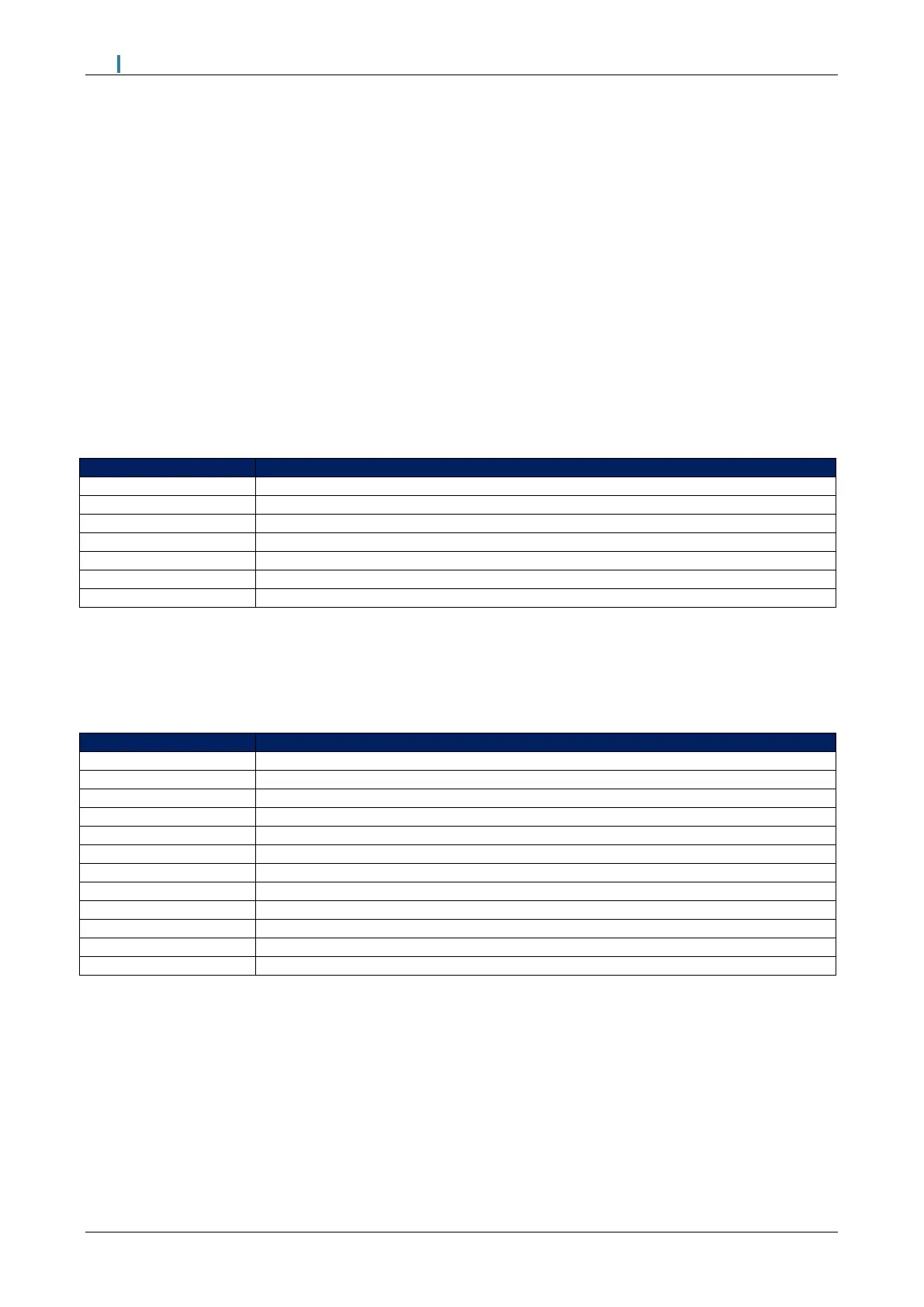
The table below shows the MM terminals for the draught servomotor and Mk8 air pressure sensor.
Digital communication connections from draught control pressure sensor
Digital communication connections from draught control pressure sensor
0V supply to draught control pressure sensor and draught control servomotor
+12V supply to draught control pressure sensor and draught control servomotor
Signal from draught control servomotor, indicating position
Switched neutral – drives draught servomotor clockwise
Switched neutral – drives draught servomotor counter clockwise
When wiring the air pressure sensor, the screen is connected through the casing of the lead and through the
sensor; therefore, the flying lead should be connected to the MM without a screen. The screen should be
carried through until the connection to the MM; the screen should not be connected to the S terminal.
The table below shows the expansions options to be set when using draught control.
Draught control servo channel
Draught servo control method
Draught servo minimum angle
Delay before compensation
Commissioned angle variation tolerance
Pressure tolerance before fault
Action on pressure sensor fault
Pressure sensor filter time

 Loading...

