11 Top Blowdown
Mk8 MM Manual Page | 213
11.5 Configuration
11.5.1 Wiring
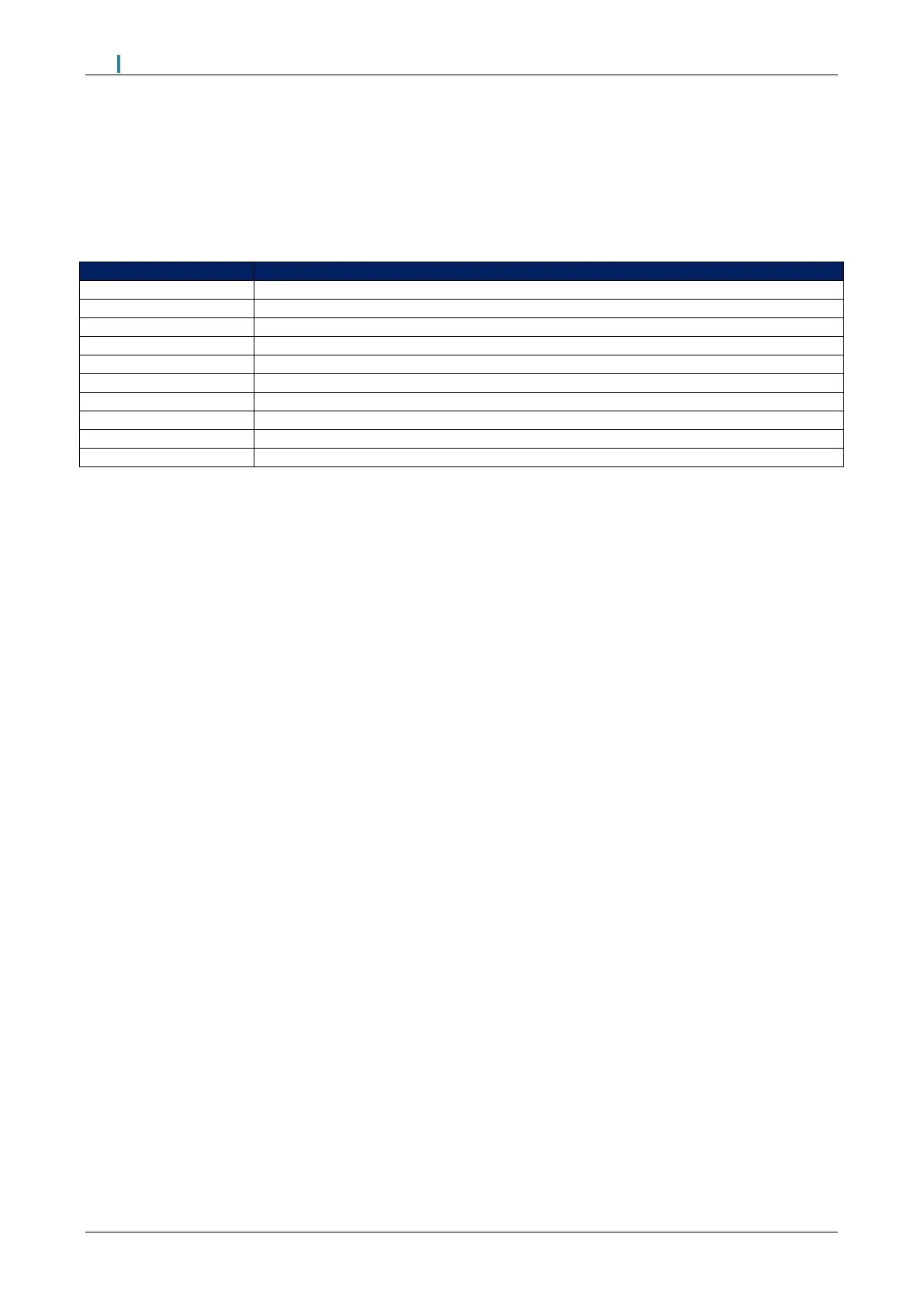
The table below indicates the terminals on the Mk8 MM allocated for Top Blowdown control.
0V supply to top blowdown and feed water servomotors
Signal from top blowdown servomotor, indicating position
+12V supply to top blowdown servomotors
Digital communications connection from TDS probe
Digital communications connection from TDS probe
Switched neutral – top blowdown contactor
Switched neutral – drives top blowdown servomotor clockwise
Switched neutral – drives top blowdown servomotor counter clockwise
11.5.2 Top Blowdown PID Controller
Top Blowdown control only makes corrections to the open time of the valve (solenoid valve, 2-state
servomotor or modulating servomotor) during blowdown time when the TDS level is within the P band
(Proportional Band set in expansion option 52).
If the current TDS level is above the P band level, the valve (solenoid valve or 2-state servomotor or
modulating servomotor) will remain fully open.
In systems with fast changing TDS level and to increase the TDS control responsiveness, the I term (Integral
time set in expansion option 53) can be decreased.
To prevent overshoot, a D term (Derivative time set in expansion option 54) can be set according to the
system requirements.

 Loading...

