10 Water Level Control
Mk8 MM Manual Page | 184
10.6.5 Configuration
The table below shows the Mk8 MM terminals allocated for the 2
nd
low safety probe.
Digital communication connections from 2
nd
low resistance probe
Digital communication connections from 2
nd
low resistance probe
+12V supply to 2
nd
low resistance probe
0V supply to 2
nd
low resistance probe
The screen is connected through the casing of the flying lead supplied with the 2
nd
low safety probe. When
connecting the flying lead to the MM, do not wire the screen at the MM.
The table below shows the expansion options to be set when using the 2
nd
low probe with the MM.
Water level control function
Note: 2
nd
low probe can only be used in conjunction with an analogue sensing device such as two
capacitance probes or one capacitance and an external level sensor at minimum; please see section 3.3
Ways of Level Sensing for more information.
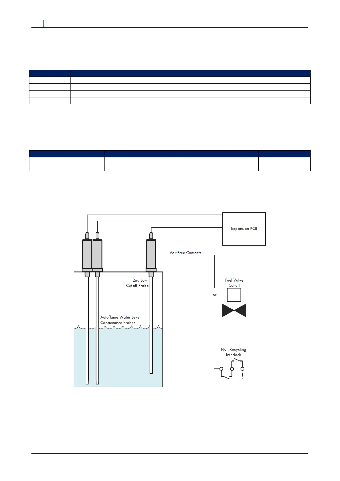
Figure 10.6.5.i 2
nd
Low Probe Installation Example
To install the 2
nd
low probe, no commissioning is required; just simply option the probe in expansion option 6.
The bottom of the 2
nd
low probe should be at the capacitance probes/external level sensor commissioned 2
nd
low level or higher.

 Loading...

