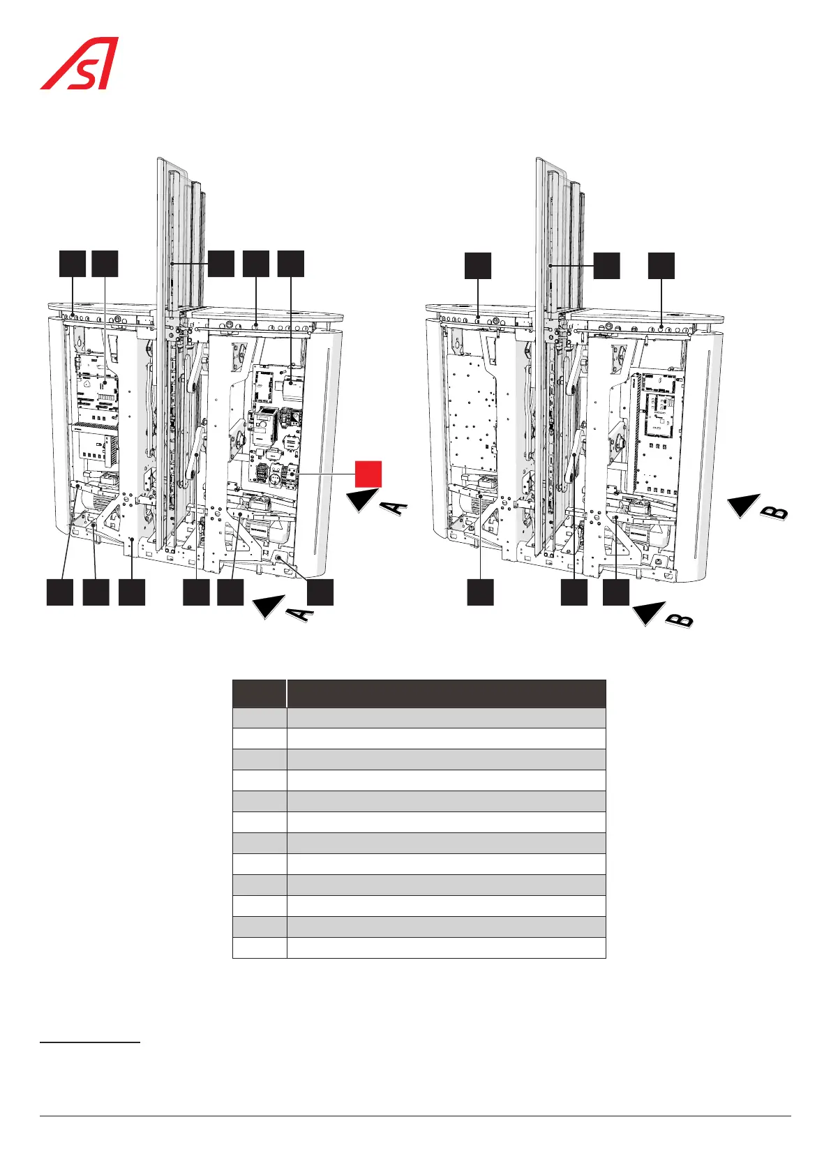
4.8.3. INTERMEDIATE CABINET
3
9
4 5
10
3
9
6
0
111 7 72 11 82 8
Fig. 12 - Location of internal components - 3
REF. DESIGNATION
0 Main circuit breaker ( Fig. 15, page 24)
1 Frame
2 Assy. DIRAS (Receiver) low plane
8
3 Assy. DIRAS (Receiver) high plane
4 Assy. Logic board, intermediate
5 Assy. Fixed obstacle detection (Receiver)
9
6 Assy. Board power ( Fig. 15, page 24)
7 Assy. Kinematics (2x)
8 Assy. DIRAS (Transmitter) low plane
10
9 Assy. DIRAS (Transmitter) high plane
10 Assy. Fixed obstacle detection (Transmitter)
11
11 Fixing clamp
8 ‘Trolley’ type reinforced DIRAS electronic detection option
9 E/R cell if mobile obstacle height = 1200 mm, DIRAS if mobile obstacle height ≥ 1500 mm.
10 ‘Trolley’ type reinforced DIRAS electronic detection option
11 E/R cell if mobile obstacle height = 1200 mm, DIRAS if mobile obstacle height ≥ 1500 mm.
22
SmartLane