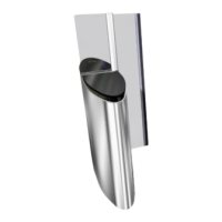
The items below refer to the Fig. 63 of the previous page.
1. Turn off the power supply to the equipment ( Chap. 8.3, page 54).
2. Then remove the right side panel - side B ( Chap. 8.3.1, page 54).
In the case of a left-hand gate, after switching off the corridor via the right-hand gate, remove the left-hand
side panels - side A and B.
In the case of an intermediate gate, after also switching off the right-hand lane via the right-hand gate, remove
the remaining panels.
3. Lock the obstacle(s) in the open position ( Chap. 8.5, page 56)
4. If the fixed obstacle is equipped with one or more aluminium profiles with security cell(s):
• For each aluminium profile, unscrew the fixing screw (3) from the top cap (4) and remove the protective screen (5) by
sliding it into the profile (6) ;
Security profile(s) with DIRAS cell:
• Disconnect the cable connecting the DIRAS electronic board to the equipment.
Safety profile(s) with REFLEX sensor:
• Unscrew the fixing screw (7) of the cell support (8) so as to disconnect the cell assembly from the fixed obstacle (9).
5. Loosen, but do not unscrew, the fixing screws (2) holding the fixed obstacle in (9) the clamp (1);
6. Pull the fixed obstacle upwards and place it in a safe position.
In the case of a fixed obstacle with a retro-reflective sensor, this will remain in place once the mobile obstacle
has been removed.
8.8. INSTALLING A FIXED OBSTACLE (AFTER POSSIBLE REPLACEMENT)
If the obstacle that has been replaced was equipped with a DIRAS cell, retrieve it from the old obstacle and
install it in the new one.
If the obstacle that was replaced was equipped with a REFLEX cell, position the cell assembly correctly in the
profile when installing the obstacle.
1. Install a new strip of crepe paper on the lower part in contact with the clamp (1);
2. Insert the fixed obstacle until it rests on the plate and/or the flap guide;
3. Tighten the screws (2);
4. Reconnect the DIRAS cell or fix the REFLEX cell support in the aluminium profile;
5. Adjust the position of the fixed obstacle ( Chap. 8.9, page 60);
6. Unlock the mobile obstacle(s);
7. Replace the side panels with the exception of the side panel - side A giving access to the power board;
8. Switch on the gate and wait for the end of the initialisation phase;
9. Check the status of the gate via the maintenance interface and mainly the status of the fixed obstacle cell. If necessary,
adjust the REFLEX cell ( Chap. 8.22, page 76);
10. Switch the device off again and fit the protective screen (5) into the aluminium profile, finishing by fitting the plug;
11. Turn on the power supply to the device;
12. Replace the right side panel - side A.
59
SmartLane