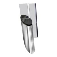
Using the W51 cable (CAN 0), connect:
• the CN8 connector of the AS1605 board, on the LEFT ( Fig. 18, page 27) or INTERMEDIATE
board
( Fig. 17, page 26)
• to the CN21 connector of the AS1603 board, on the RIGHT ( Fig. 16, page 25) or INTERMEDIATE
board
( Fig. 17, page 26)
LEFT or INTERMEDIATE gate
CN8 (AS1605)
RIGHT or INTERMEDIATE gate
CN21 (AS1603)
(See electrical diagrams 2SL204.002A 2SL204.003A(See electrical diagrams 2SL204.002A 2SL204.003A
W51
Fig. 32 - Inter-cabinet connection - W51
CONNECT THE SHIELDING PROPERLY!
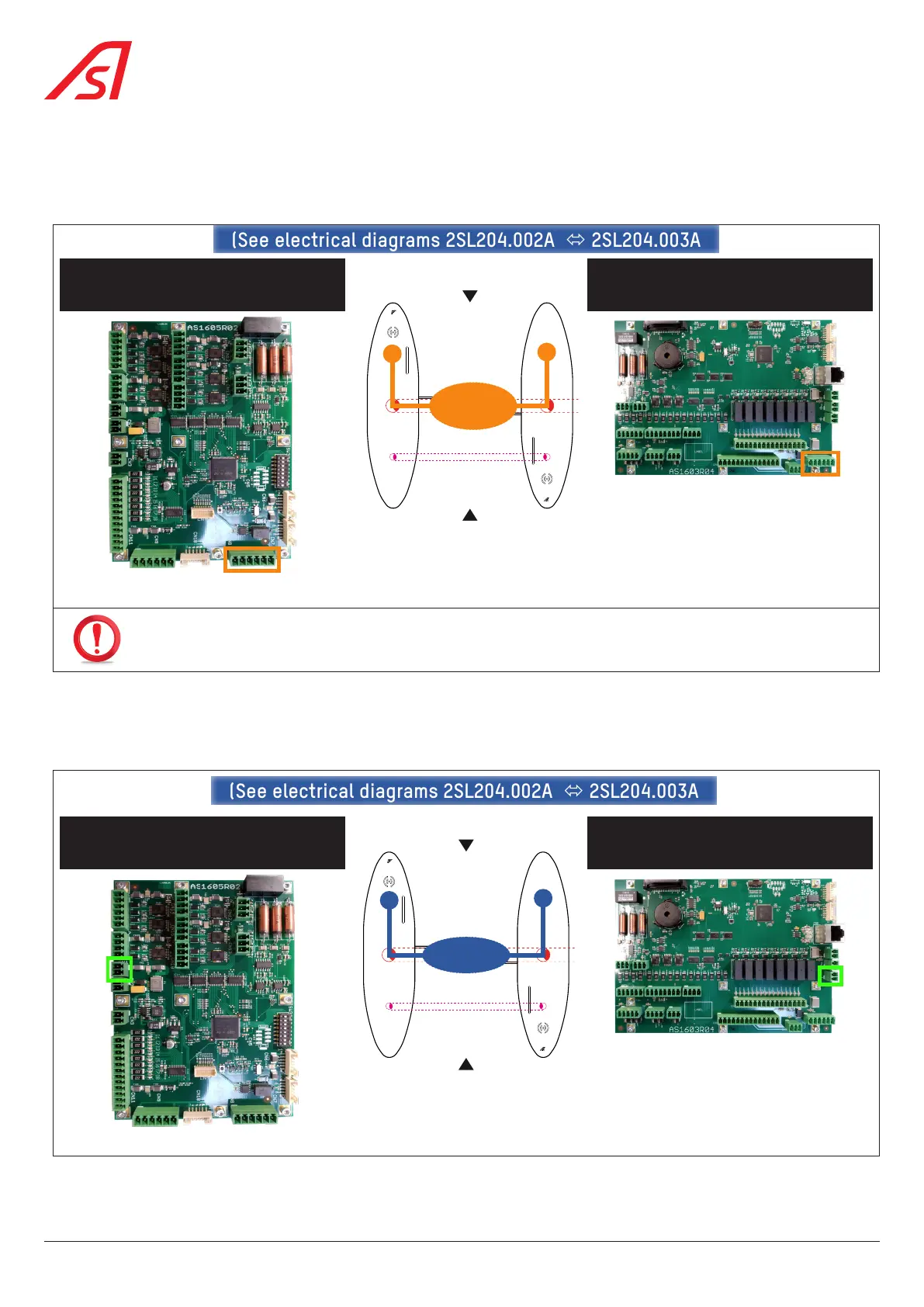
Using the W23 cable (24 VDC), connect:
• the CN1 connector of the AS1605 board,on the LEFT ( Fig. 18, page 27) or INTERMEDIATE
board
( Fig. 17, page 26)
• to the CN3 connector of the AS1603 board, on the INTERMEDIATE ( Fig. 17, page 26) or RIGHT
board
( Fig. 18, page 27)
LEFT or INTERMEDIATE gate
CN1 (AS1605)
RIGHT or INTERMEDIATE gate
CN3 (AS1603)
W23
(See electrical diagrams 2SL204.002A 2SL204.003A(See electrical diagrams 2SL204.002A 2SL204.003A
Fig. 33 - Inter-cabinet connection - W23
36
SmartLane