96
SmartLane
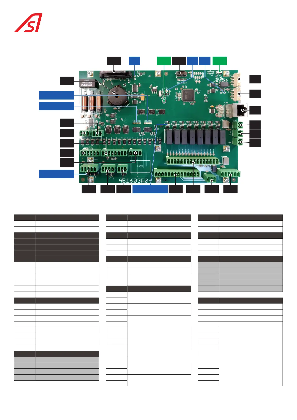
9.4. AS1603 CIRCUIT BOARD - MAIN AND E/S INTERFACE BOARD
CN11
BZ1
CN13
CN14
CN12
CN10
CN6
CN7
CN8
CN1
CN2
CN3
SW4CN9 CN4SW2
CN16 CN17CN15 CN20 CN21CN19 CN18LD12 > LD19
LD4 > LD11
LD20 > LD27
LD28 > LD33
LD3 LD1 LD2
Fig. 108 - AS1603 circuit board - Main and E/S interface board
BZ1: buzzer with adjustable volume and tone via the Maintenance Interface.
CN1 24 VDC POWER SUPPLY CN2 24 VDC POWER SUPPLY CN3 24 VDC POWER SUPPLY
1 +24 VDC 1 +24 VDC 1 +24 VDC
2 GND 2 GND 2 GND
CN6 CAN 0 BUS CN10 TRANSMITTER CELLS CN11 MOT1 POSITION SENSOR
CN7 CAN 1 BUS 1 +24 VDC 1 +24 VDC
CN8 RJ45 ETHERNET LINK. 2 S 2 S
CN9 CPU INTERFACE 3 GND 3 GND
CN12 ADDITIONAL INPUTS CN14 EMERGENCY CN15 NOT USED
1 +24 VDC 1 Emergency loop 1 +24 VDC
2 +24 VDC 2 GND 2
3 E9 3 +24 VDC 3
4 E10 4 E8 (Emergency button) 4
5 E11 CN18 RELAIS 5 GND
6 E12 1
Relay contact 1 (Direction of
passage A)
CN13 ADDITIONAL INPUTS 2 CN19 INPUTS
1 +24 VDC 3
Relay contact 2 (Direction of
passage B)
1 EI (Locked open)
2 +24 VDC 4 2 E2 (Locked closed)
3 E13 (Authorization in direction A) 5
Relay contact 3 (Obstacles closed)
3 E3 (Free mode A)
4 E14 (Authorization in direction B) 6 4 E4 (Free mode B)
5 E15 7
Relay contact 4 (Technical failure)
5 E5 (evacuation)
6 E16 8 6 E6
7 GND 9
Relay contact 5 (Locking of card
reader A)
7 E7
8 GND 10 8
+24 VDC
CN16 NOT USED 11
Relay contact 6 (Locking of card
reader B)
9
1 +24 VDC 12 10
2 13
Relay contact 7 (Fraud & Intrusion)
11
3 14 12
4 GND 15
Relay contact 8
13
16 14