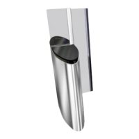
Connect the motor cable W31 of the left gate to the dedicated terminal on the board power of right gate.
OFF OFF
L N
1 3
2 4
PE
IN
W4
W3
W7
W6
W5
W2
W0
W9
W8
W10
PE N L
PE
U V W
N L PE
W30
W29
U
31
W31
44 1 2 32
V
W
LEFT or INTERMEDIATE gate RIGHT or INTERMEDIATE gate
W31
See electrical diagram 2SL204.001ASee electrical diagram 2SL204.001A
Fig. 34 - Inter-cabinet connection - W31
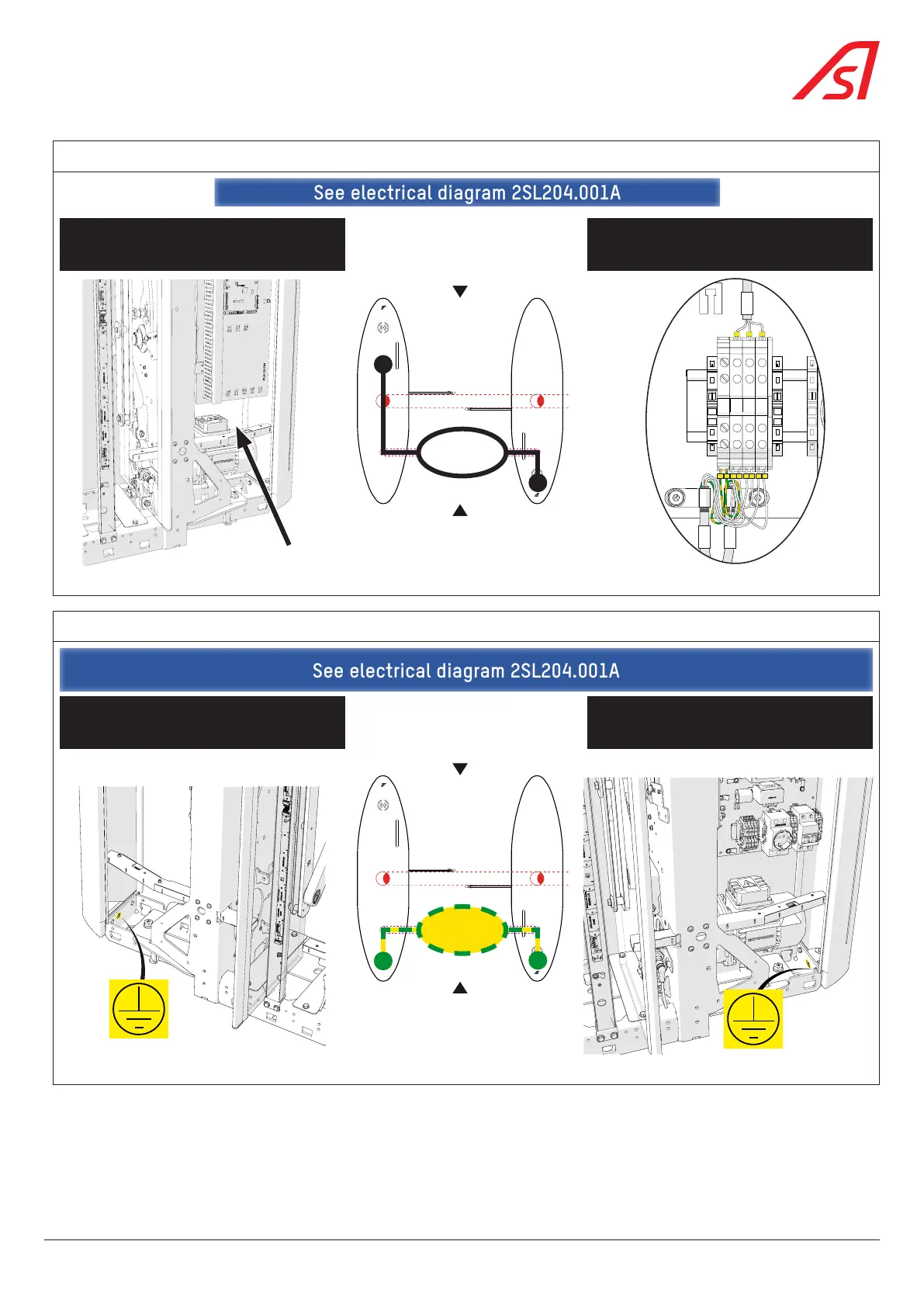
Install the equipotential bonding between both frames using cable W58.
LEFT or INTERMEDIATE gate RIGHT or INTERMEDIATE gate
W58
See electrical diagram 2SL204.001ASee electrical diagram 2SL204.001A
Fig. 35 - Inter-cabinet connection - W58
37
SmartLane