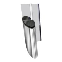
3. If the top of the fixed glass panel is to be moved to side A:
• On side B, unlock, but do not unscrew , the fixing screws (2) holding the obstacle in the clamp (1);
• Slightly tighten the two (2) set screws A and A' on side A, to straighten the obstacle towards side A .
• Tighten the fixing screws (2) on side B and check the parallelism between the fixed obstacle and the mobile obstacle.
A A'
Fig. 65 - Straightening the mobile obstacle (To side A)
• Lock the positioning of the fixed obstacle by securing the corresponding locknuts.
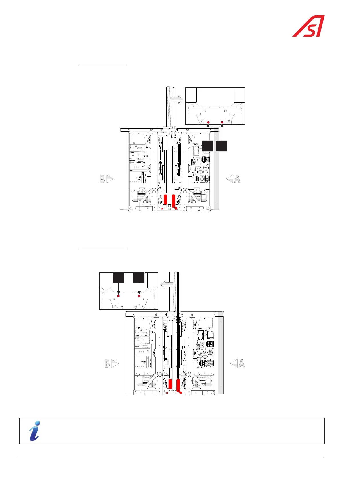
4. If the top of the fixed glass panel is to be moved to side B:
• On side B, unlock, but do not unscrew , the fixing screws (2) holding the obstacle in the clamp (1);
• Slightly tighten the two (2) set screws B and B' on side B, to straighten the obstacle towards side B .
• Tighten the fixing screws (2) on side B and check the parallelism between the fixed obstacle and the mobile obstacle.
B B'
Fig. 66 - Straightening the mobile obstacle (To side A)
• Lock the positioning of the fixed obstacle by securing the corresponding locknuts.
When installing the fixed glass panel for the first time (without prior adjustment), first check the adjustment
of the fixed glass panel with the screws A, A', B and B’unpressurised (loose) and with the screws (2) tightened.
61
SmartLane