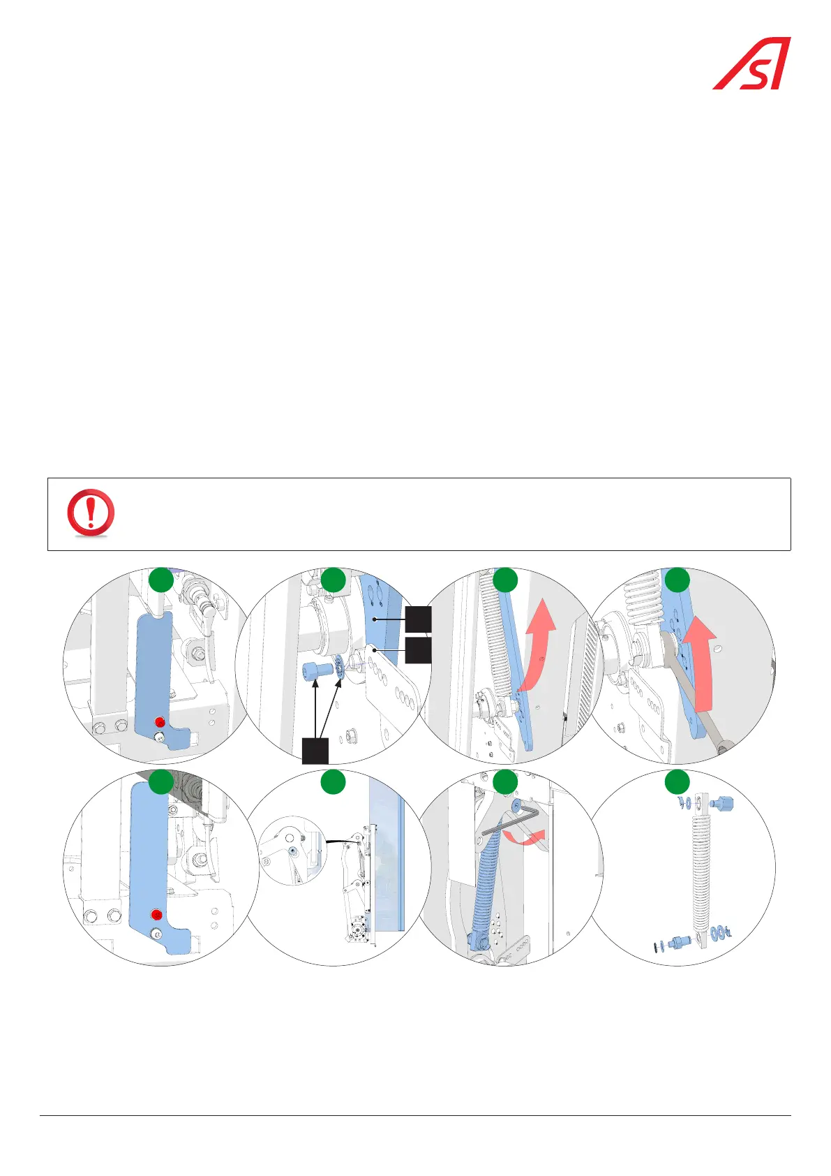
8.24. REPLACING AND ADJUSTING THE BALANCE SPRING
8.24.1. REPLACING THE SPRING
1. Remove the right side panel on side A ( Chap. 8.3.1, page 54);
2. Turn off the power supply to the device. ( Chap. 8.3, page 54). If necessary, also cut the power supply to the adjacent lane;
3. Manually move the kinematics to the open position (obstacle fully retracted into the housing);
4. Lock the position of the obstacle ( Chap. 8.5, page 56) ; [A]
5. Remove the fixing elements (1) from the compass (2) on the compass mount (3); [B]
6. Rotate the compass to allow for slow dissipation of any potential energy still present in the balancing spring; [C]
7. Using a 20 mm spanner, unscrew the lower spring pivot from the compass; [D]
8. Manually place the kinematics in the closed position (obstacle completely out of the housing) and lock the mobile obstacle;
[E]
The kinematics positioned in this way allows easy access to the upper pivot fixing screw; [F]
9. Remove the upper pivot fixing screw and remove the spring; [G]
10. Remove the clips and washers from the upper and lower pivots and remove both pivots; [H]
IN AN INTERMEDIATE UNIT, IT WILL BE NECESSARY TO LOCK THE ADJACENT LANE OBSTACLE ALSO IN THE CLOSED
POSITION TO GAIN ACCESS TO THE UPPER PIVOT OF THE SPRING ASSEMBLY SAFELY!
D
H
CA
GFE
B
2
3
1
Fig. 93 - Removing the spring
11. Follow the same process in the reverse order for reassembly and, if necessary, do not release the obstacle in the adjacent
lane until the last moment.
81
SmartLane