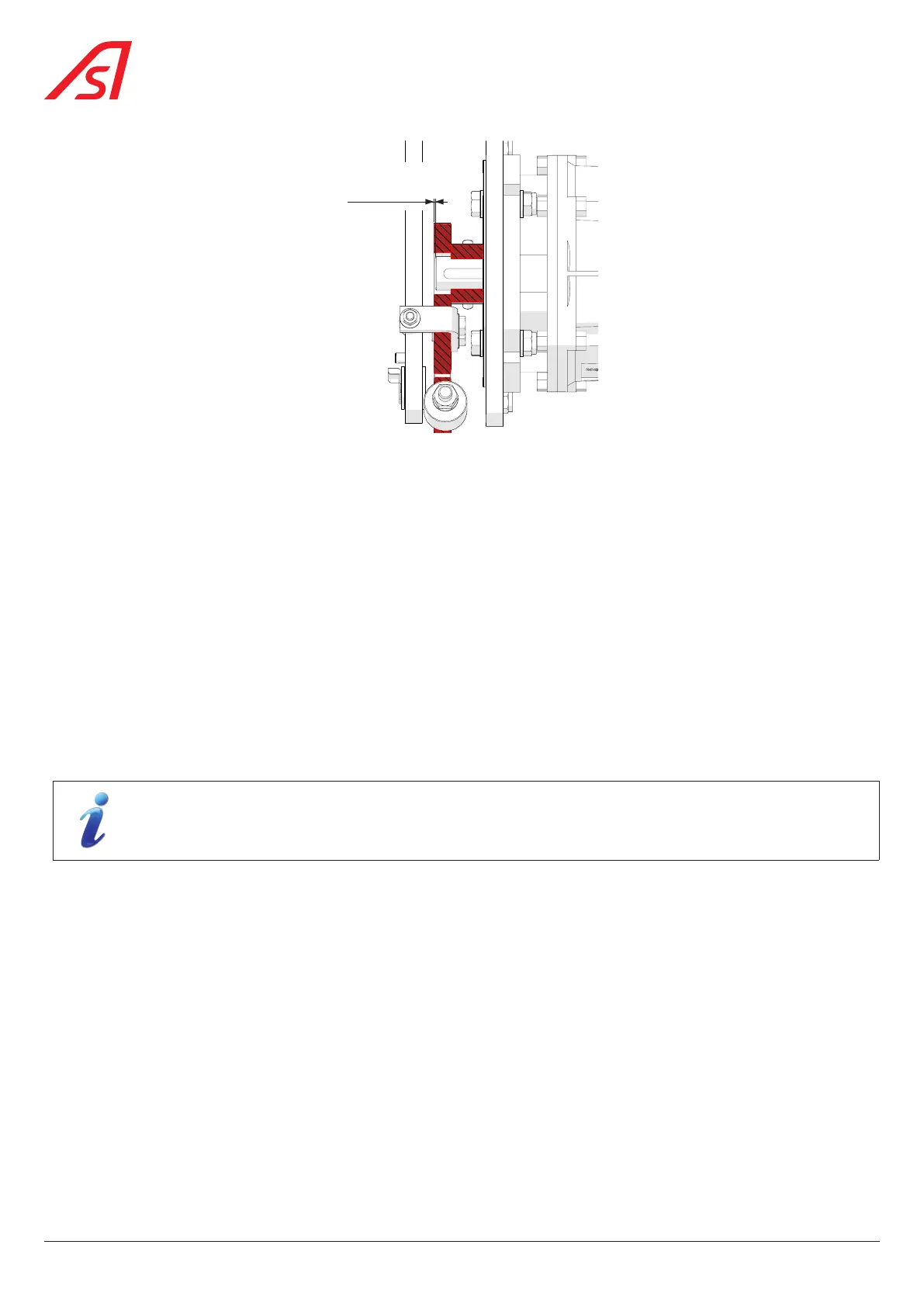
0,8 mm
Fig. 87 - Adjusting the motor crank (Alignment)
To realign the crank on the motor shaft:
1. Loosen the two (2) set screws;
2. Move the crank handle in the desired direction on the motor shaft;
3. Tighten the set screws;
4. Manually move the mobile obstacle and check that the movement is free and without excessive friction.
5. Also check that the system unlocks correctly during a power failure.
8.22. REMOVING AND ADJUSTING THE DETECTION PHOTOCELLS
On the SmartLane in general, detection is carried out by straight and curved DIRAS cells.
However, for the following two (2) cases, detection is carried out by a classic Transmitter/Receiver type cell:
- In the case of a fixed obstacle with a height of 1200 mm, in relation to the floor;
- In the case of early opening detection, in the foot of the extensions.
The Transmitter photocells are located in the gate on your right in direction A;
The Receiver photocells are located in the gate to your left in direction A.
The location of the photocells is shown in Chap. 6.2.1.
76
SmartLane