9.3. MOTHERBOARD (CPU) AS1190
CN7 CN1LD1 LD6
LD2
LD3
LD4
CN9
CN5CN10 LD5CN12CN11 CN3
CN6
CN4
S4 S1 S3 S2CN14 CN13
CN16CN2
ETH1 ETH2
i
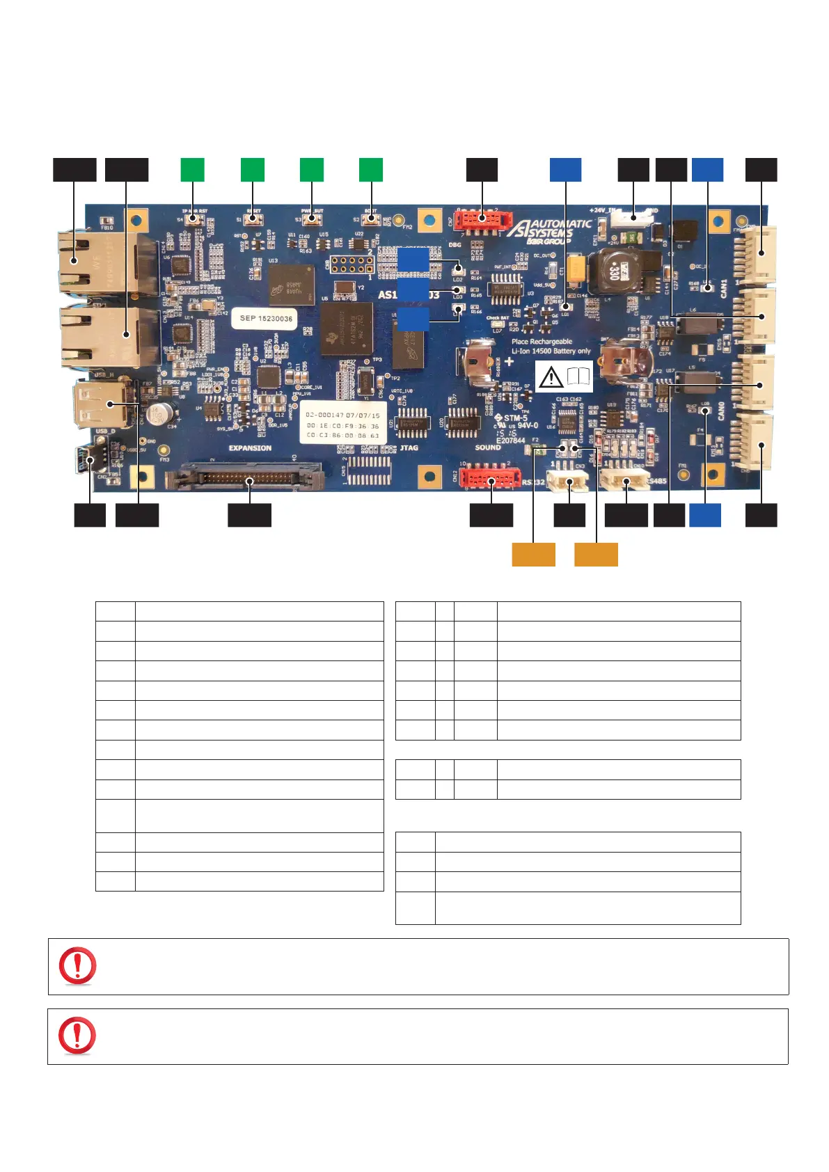
Fig. 107 - Motherboard AS1190
CN1
24 VDC power supply.
LD1
Green Voltage present indicator light.
CN2
USB device.
LD2
Yellow EMMC memory access.
CN3
RS232 link.
LD3
Green LED user.
CN4
CAN 0 Bus.
LD4
Red CPU activity (heartbeat) indicator light.
CN5
CAN 0 Bus.
LD5
Yellow CAN 0 bus node status indicator light.
CN6
CAN 1 Bus.
LD6
Yellow CAN 1 bus node status indicator light.
CN7
COM serial debug link
LD7
Red Incorrect battery position indicator light.
CN9
CAN 1 Bus.
CN10
RS485 link.
ETH1
Yellow Ethernet connector 1 activity indicator light.
CN11
I/O extension BUS.
ETH2
Yellow Ethernet connector 2 activity indicator light.
CN12
I2S interface with the AS1106 circuit board.
(Text-to-speech card)
CN13
Ethernet100 Mbps RJ45 link.
S1
CPU Reset.
CN14
Ethernet100 Mbps RJ45 link.
S2
Program Restart.
CN16
USB 2.0 host
S3
Shutdown.
S4
Recovery of factory IP address (192.168.0.200) if pressed at
start-up or for 20 sec.
IF LED LD7, WHICH INDICATES THE INCORRECT POSITION OF THE BATTERY, IS LIT (RED), INVERT THE POSITION OF THE
BATTERY IN ITS HOLDER.
RISK OF EXPLOSION IF BATTERY IS REPLACED BY AN INCORRECT TYPE. DISPOSE OF USED BATTERIES IN ACCORDANCE
WITH THE INSTRUCTIONS IN ( CHAP. 8.33, PAGE 93).