3
3'
1
5
2
4
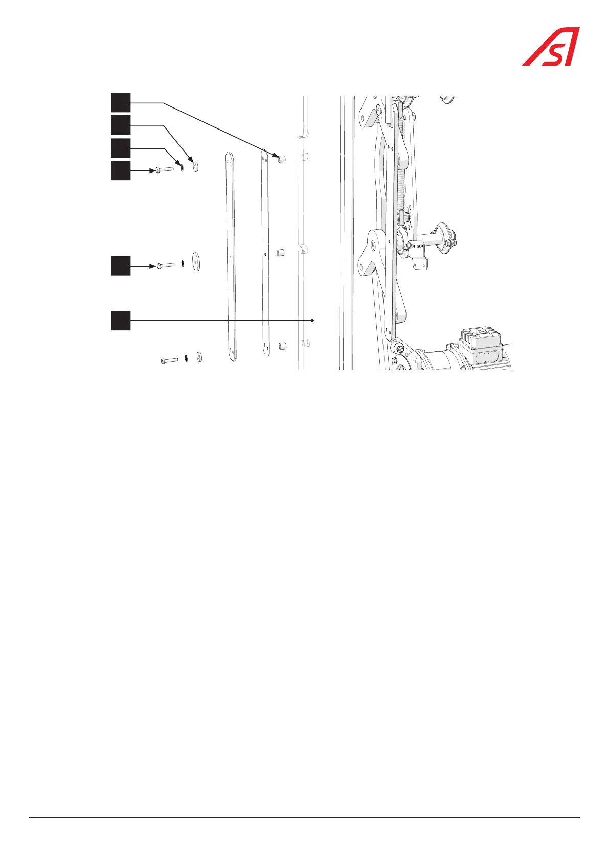
Fig. 68 - Fixing elements for mobile obstacle
4. Loosen screw (3') partially (without removing it);
5. Unscrew the two (2) screws (3) completely and remove the associated washers (4) and (5), taking care to hold the obstacle
to prevent it from tipping over;
6. Remove the mobile obstacle (1) by bringing it back to the centre of the lane;
7. Place the nozzles (2) in the new mobile obstacle and, if necessary, replace the nozzle associated with the screw (3');
8. Insert the new obstacle by resting on the screw 3’ and replace the different elements;
9. Adjust the verticality of the mobile obstacle before finally tightening the three (3) fixing screws (3) and (3');
10. Unscrew the locking screw (C) to release the kinematics.
11. Replace the panels, keeping the right panel - side A - for the end and taking care to reconnect the various ground braids;
12. Turn on the power supply to the device ( Chap. 8.3, page 54);
13. Replace the right panel - side A once the initialisation has been completed, taking care to reconnect the various ground
braids.
63
SmartLane