8.10. REMOVAL / INSTALLATION OF THE MOBILE OBSTACLE
13
Ratchet wrench with extension and 17 socket + Circlip pliers + Allen key set.
Depending on the size of the obstacle, a second person may be required to safely perform this operation.
1. Switch off the equipment ( Chap. 8.3, page 54);
2. Then remove the side panel(s) on either side of the movable obstacle to be replaced ( Chap. 8.3.1);
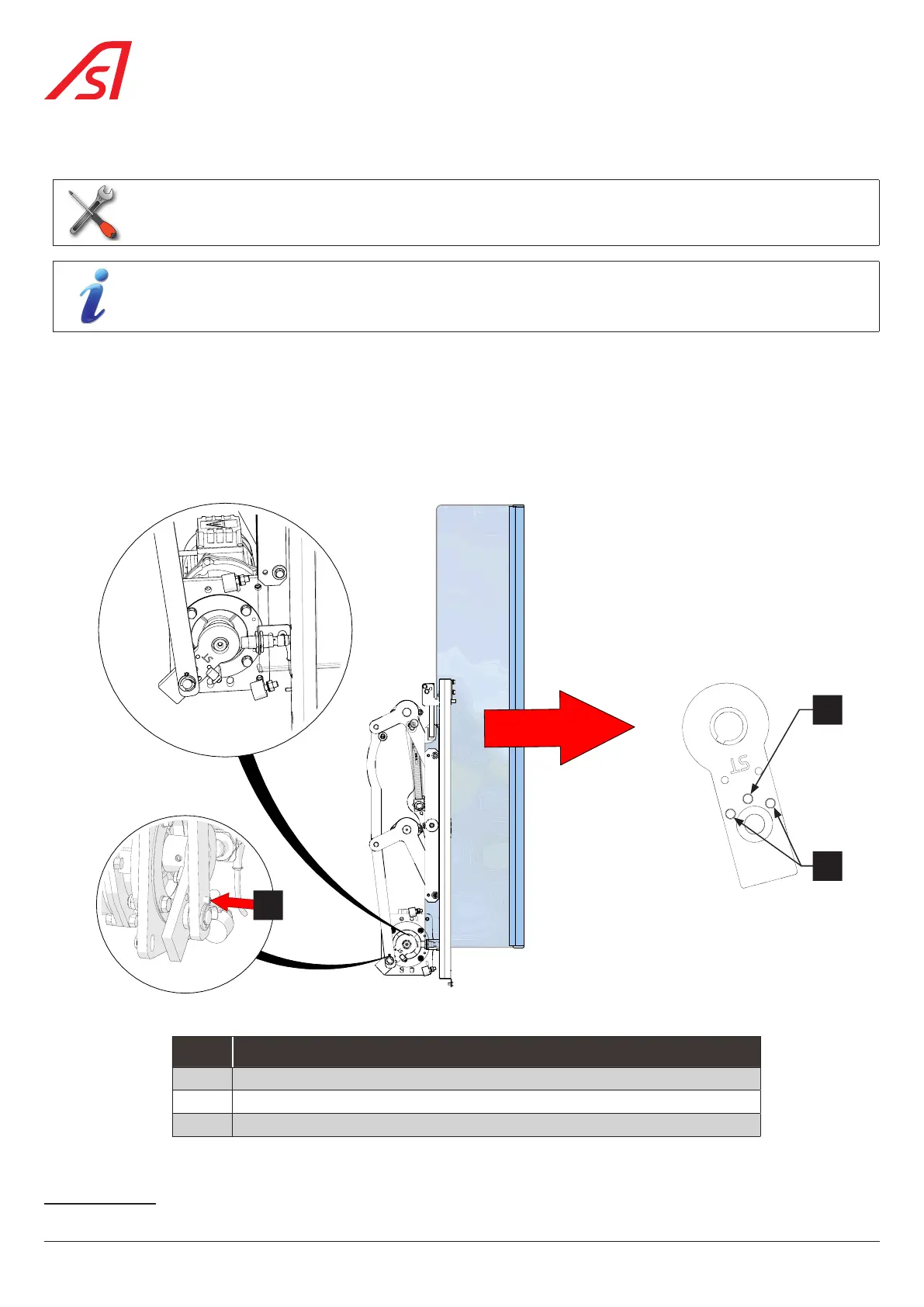
3. As the mobile obstacle has opened and fully retracted into the body, pull the obstacle forward so as to align one of the
crank locking holes
13
(B) with the one on the lower connecting rod. Screw in the stainless steel set screw (C) until it is
sufficiently tight in the crank hole.
This will allow you to work without the risk of the mechanism moving and the baseboard will be correctly positioned, behind
the vertical DIRAS detection, making the anchoring points of the mobile obstacle accessible;
A
B
C
Fig. 67 - Replacing the mobile obstacle
REF. DESIGNATION
A Hole for locking the mobile obstacle in the open position
B Holes for locking the mobile obstacle in the maintenance position
C Locking screw
13 Depending on the type of mechanism: left or right.
62
SmartLane