IT IS ESSENTIAL TO ADAPT THE ANCHORS AND THE ANCHORING PROCEDURE TO THE ENVIRONMENT AND THE TYPE
OF SURFACE ON WHICH THE EQUIPMENT WILL BE MOUNTED. FURTHERMORE, IT IS ESSENTIAL THAT THE WORK BE
APPROVED BY AN ENGINEER SPECIALIZED IN THE FIELD.
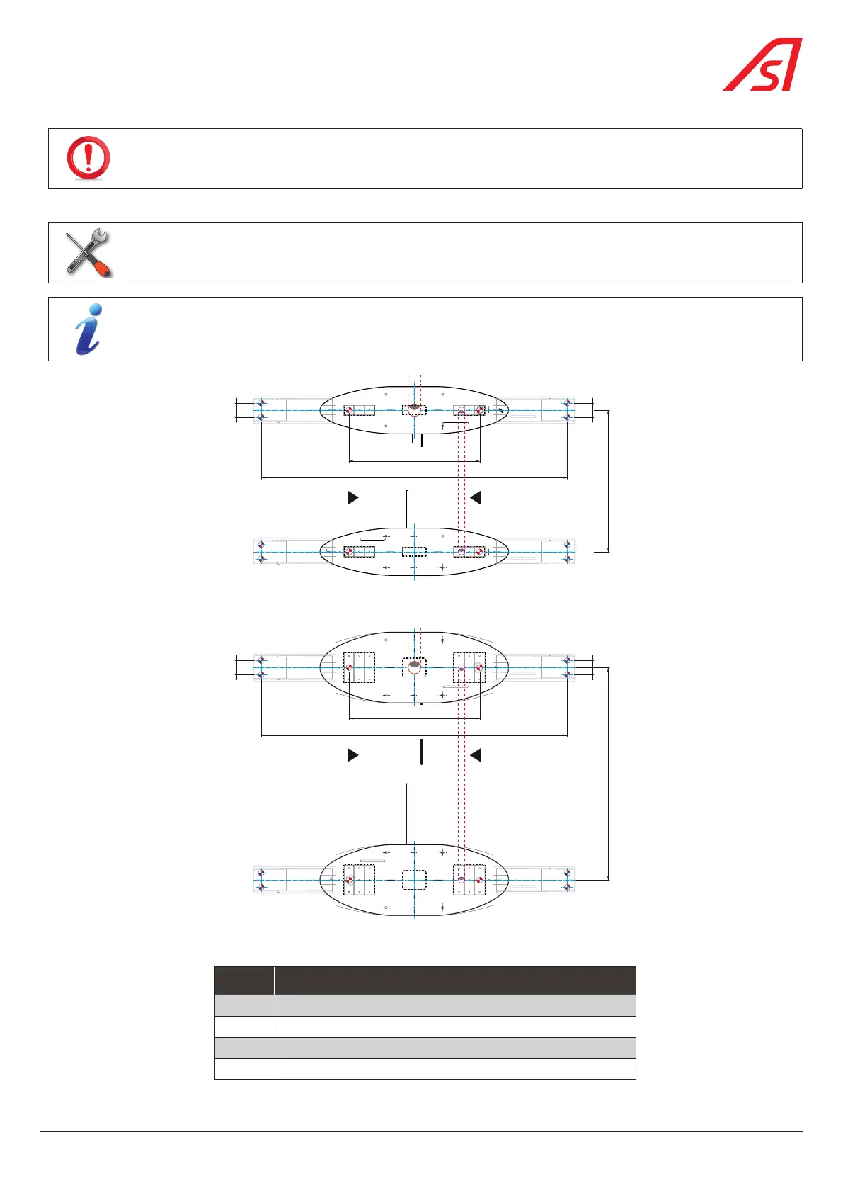
1. Mark the anchoring points of the equipment on the floor, referring to the installation drawing, Chap. 5.6, page 30.
13
Drill + drill bits suitable for the type of floor + mallet (if necessary).
The packaging used to protect the product during transport includes a template that can be used when
marking the anchoring points of the device.
G
A
B
-
E
-
0
1
0
8
3
0
7
1 1
4
3
4
= 831 =
G
A
B
-
E
-
0
1
0
8
3
0
7
1 1
4
3
4
A
B
2
2
2
2
GAB-E-0108349
GAB-E-0108349
= 1946 =
900
90
90
2
2
2
2
GAB-E-0108349
GAB-E-0108349
Fig. 27- Marking the anchoring points for the Standard SmartLane with template(s)
G
A
B
-
E
-
0
1
0
8
3
1
0
C
= 831 =
1
3
4 4
1
G
A
B
-
E
-
0
1
0
8
3
1
0
C
1
4
3
4
1
A
B
2
2
2
2
GAB-E-0108349
GAB-E-0108349
= 1946 =
90
90
2
2
2
2
GAB-E-0108349
GAB-E-0108349
1350
Fig. 28 - Marking the anchoring points for the Wide SmartLane with template(s)
REF. DESIGNATION
1 Cabinet anchoring points
2 Anchoring points for optional extension(s)
3 (Central) routing area for power cables
4 (Lateral) routing area for inter-cabinet cables
33
SmartLane