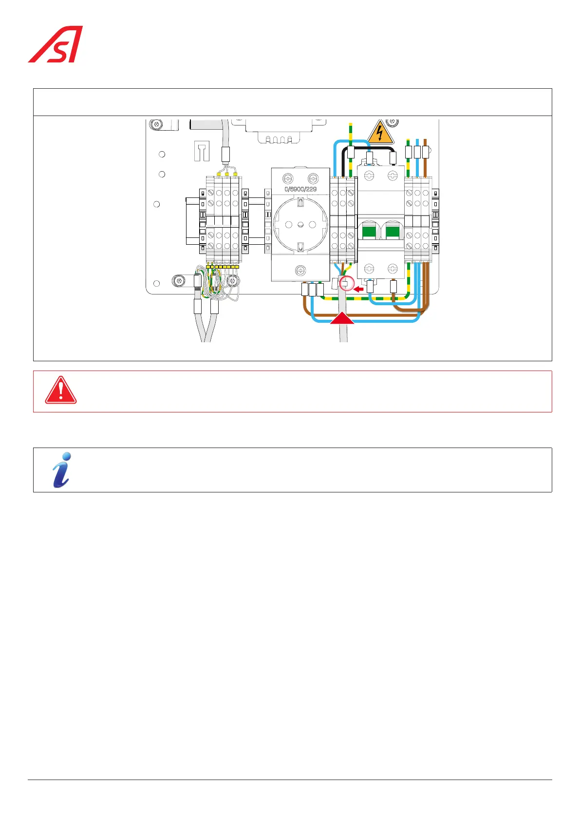
Connect the two (2) phases of the power supply (single phase 120/230 VAC - 50/60 Hz) and the ground to the main terminal
block using a cable with min. cross section 2.5 mm². Protect the upstream line with a 16A circuit breaker.
OFF OFF
L N
1 3
4
PE
IN
2
W7
W6
W5
W9
W8
W10
N L
PE
U V W
PE
W30
W29
U
31
W31
44 1 2 32
V
W
PE L1N
W2
W1
W0
W3
W4
Fig. 36 - Connection to the main terminal block
NB!
USE THE HOLE DIRECTLY BELOW AND TO THE RIGHT OF THE CIRCUIT BREAKER TO SECURE THE MAINS CABLE TO THE
BOARD WITH A PLASTIC CLAMP.
5.10. COMMISSIONING
If the equipment was stored with power off and ambient temperature below 15 °C (5 °F), it is important to
allow it to warm up for 30 minutes to one (1) hour before powering up.
Switch on the main circuit breaker to power up the equipment. ( Chap. 8.3, page 54)
On power-up, the obstacles will go through an opening and closing cycle to determine the end opening positions of the product.
During the restart phase, the dynamic orientation lights are fixed red and the dynamic status lights are switched off, giving way
to the configuration defined in the Maintenance Interface once the product is operational.
If necessary, configure the lane via the Maintenance Interface (opening speed, mode, colour of the dynamic lights, etc.) see
specific manual.
Perform several openings and closings using the available controls (reader, remote control, etc.) and check the obstacle
position in the open and closed positions.
Check that the obstacles open completely when an evacuation order is issued.
Pass through several times and check that the pictograms and buzzer operate properly.
Check that the optional equipment (monitoring panel, etc.) and customer-incorporated equipment (reader, etc.) is operating
correctly.
38
SmartLane