5. INSTALLATION
THE INSTALLATION WORK MUST BE CARRIED OUT IN ACCORDANCE WITH LOCAL STANDARDS, SAFETY INSTRUCTIONS
( PAGE 8) AND THE INSTALLATION PLAN BELOW.
5.1. ON-SITE WORK PREPARATION
The SmartLane range of gates is designed to be installed inside buildings, protected from the weather.
The preliminary installation work on the equipment must be carried out in accordance with the installation plan ( Chap. 5.6).
This applies in particular to the laying of conduits for electrical cables ( Chap. 5.6).
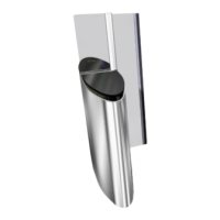
5.2. FLOOR LEVELLING GUIDELINES
The gate must be mounted on a concrete or other non-combustible material floor that is resistant to the torque applied by
tightening the anchor bolts (50 Nm).
The floor must be perfectly flat (no bumps). The maximum allowed (longitudinal and transverse) slope between the units is 2°
(to ensure transmission of the detection beams). The slope must be constant (no change in direction allowed).
The slope should be the same for all gates in a series.
2° Max.
2° Max.
Fig. 19 - Maximum slope - Front view Fig. 20 - Maximum slope - Side View
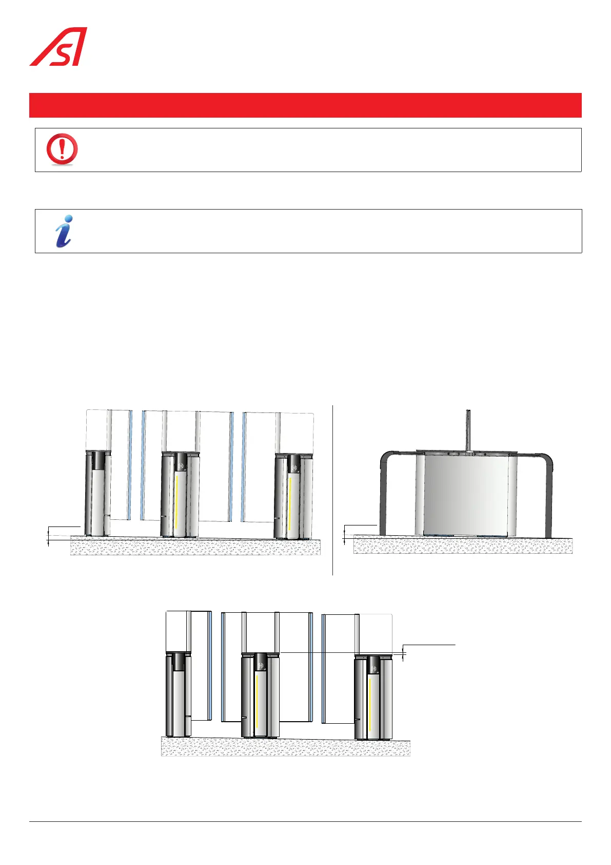
5.3. MAXIMUM FLATNESS TOLERANCE OF THE FLOOR FROM CABINET TO CABINET
Fig. 21 - Maximum flatness tolerance
• If this tolerance is exceeded ( Fig. 22), the floor must be levelled with grout before the gates are installed.
28
SmartLane