6.3. MECHANICAL TRANSMISSION OF MOTION
Each mobile obstacle is controlled by its own geared motor. The intermediate gates thus contain two (2) geared motors,
controlled by two (2) different logics (one (1) per lane).
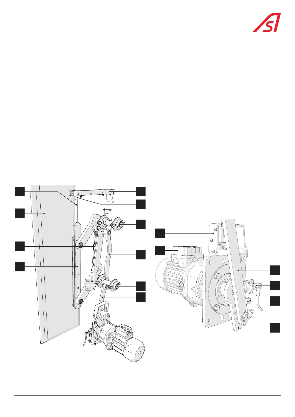
The movement of the geared motor (6) is transmitted to the mobile obstacle (1) by means of a connecting rod (8) / crank (5)
system linked to the lower (9) and upper (12) shafts by means of a secondary connecting rod (10). This system also ensures the
mechanical locking of the obstacle in both positions (open and closed) by the alignment of the connecting rod and the crank:
it is then impossible to open the obstacle manually.
The baseboard (2), which connects the mobile obstacle to the upper and lower shafts, is used to secure the mobile obstacle.
It is equipped with a guide tube (15) at the top, which connects to the tie rod (14) of the flap that is fitted to the gate when the
height of the moving obstacle is greater than 1 metre.
The flap, which slides in the flap guide (13), closes the passage area of the moving obstacle in the upper part of the gate.
The angular position of the unit (and thus of the obstacle) is transmitted to the control logic by an inductive sensor (3) measuring
the distance separating it from the crank (5) (which has a spiral form on the crankshaft.
A preloaded balance spring (11) assists the geared motor both for opening and closing the obstacle.
In the event of a power failure, an intrinsic mechanical device ensures the automatic opening of obstacles. This device consists
of a compressible mechanical rubber stop (4) and is assisted by the balance spring(s).
As an option, an electromagnetic locking system (7) makes it possible, in the event of a power failure, to block the crank in
order to lock the obstacle in the open position (obstacle completely retracted into the body).
6
7
3
4
5
8
11
1
2
13
12
10
8
9
14
15
Fig. 47 - Transmission of motion
45
SmartLane