8.22.1. REMOVING THE PHOTOCELL FROM THE FIXED OBSTACLE
To access the high security photocell (fixed obstacle H > 1200) of the lane in question, it is necessary to:
1. Remove the right side panel - side A ( Chap. 8.3.1, page 54);
2. Turn off the power supply to the device ( Chap. 8.3, page 54);
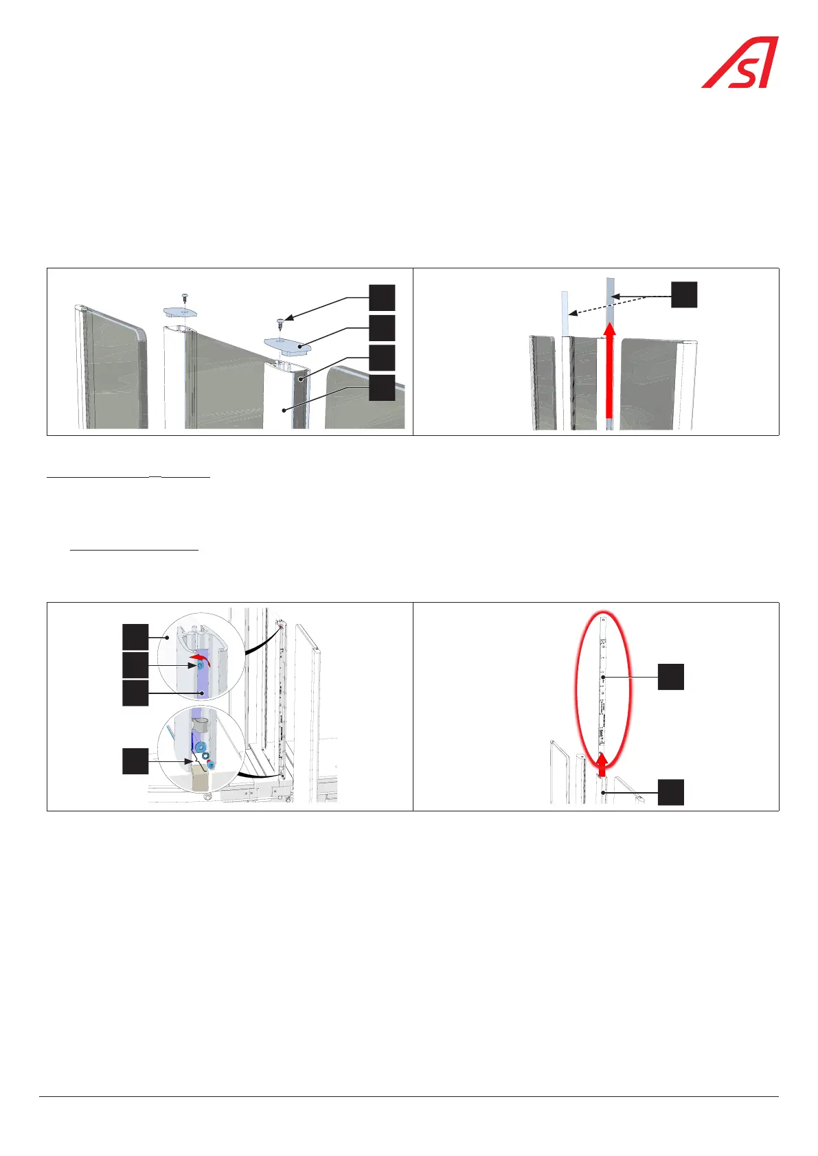
3. On the side of the cell to be replaced, unscrew the fixing screw (3) from the top plug (4) and remove the protective screen (5)
by sliding it out off the aluminium profile (6) ( Fig. 88);
4
5
6
3
5
Fig. 88 - Removing the plug(s) and screen(s) of the fixed obstacle
For a DIRAS cell: ( Fig. 89)
4. Disconnect the cable connecting the DIRAS electronic board to the equipment;
5. Remove the fixing elements (10) of the cable on the cell support;
6. Without unscrewing it, loosen the pressure screw (7) of the cell support (8) so as to disconnect the cell assembly from the
fixed obstacle (9);
7. Remove the DIRAS support assembly by sliding it upwards into the aluminium profile (6).
8
9
7
10
6
8
Fig. 89 - DIRAS cell removal
8. Place the new cell on the support and replace the assembly in the aluminium profile;
9. Make the various connections (cell cable and earth connection);
10. Fix the cell assembly in the aluminium profile;
11. Replace the side panels with the exception of the side panel - side A giving access to the power board;
12. Switch on the gate and wait for the end of the restart phase;
13. Check the status of the gate via the maintenance interface and mainly the status of the fixed obstacle cell.
77
SmartLane