Installation and Upgrades for DEFINITY ONE and
IP600 Internet Protocol Release 10
555-233-109
Issue 6
December 2001
Install and Cable the Cabinet
1-112Connect external alarms and auxiliary connections
1
Emergency transfer and auxiliary power
NOTE:
Only 1 emergency transfer power panel and 1 auxiliary power connection
are provided per system.
Connect emergency transfer power and auxiliary power as shown in Table 1-19.
Auxiliary power includes power to an Attendant Console or adjunct device.
Telephone pin designations
Table 1-20 provides pack and pin designations.
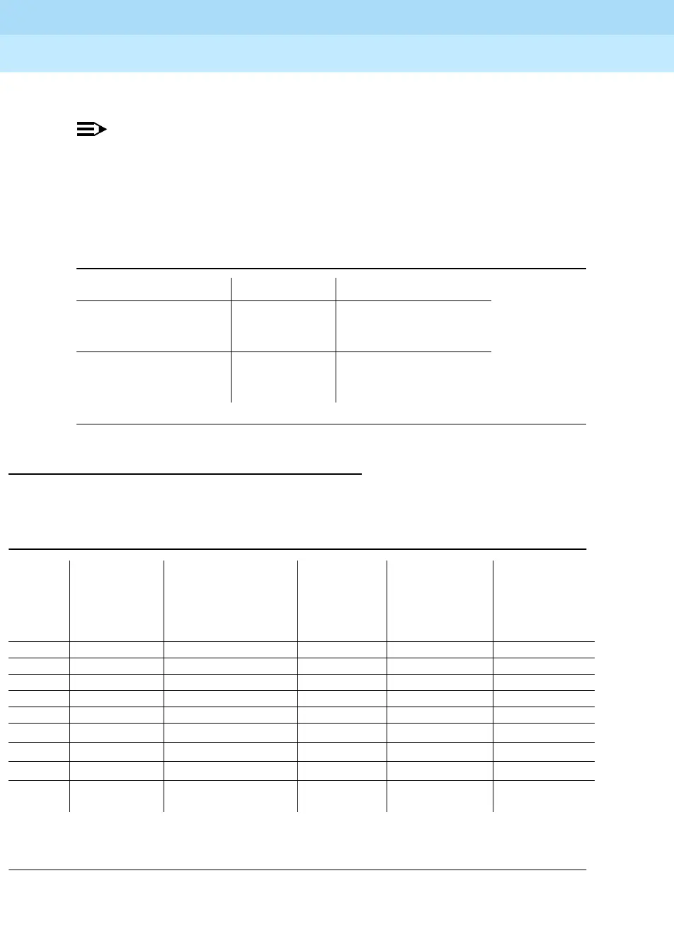
Table 1-19. Emergency transfer and auxiliary power
Power type Color AUX connector
Emergency Transfer Black-Blue XFER48 (Pin 36)
Blue-Black Ground (Pin 46)
Adjunct -48 VDC Brown-Yellow ACC48A (Pin 19)
Yellow-Brown Ground (Pin 44)
Table 1-20. Port circuit pack and telephone pin designations
Pin on
Modular
Plug
4-wire;
302C1,
8400-Series,
603E, 9403,
9434
2-wire; 302C1,
8400-Series, 603E,
9403, 9410, 9434
8510T BRI
(with adjunct
speaker
phone)
Analog Station,
Modem
Z3A1 & Z3A2
ADU, Data
Module
1TXT TXT
2 TXR T TXR
3 PXT TXT R PXT
4 T PXR
5 R PXT
6 PXR TXR PXR
7 -48VDC (-48VDC) (-48VDC)
8 GRD GRD GRD
circuit
pack
4-wire digital
(8 ports)
2-wire digital
(16 or 24 ports)
4-wire BRI
Trunk Side
Analog line
(16 or 24 ports)
Data Line
PX PBX transmit T Tip (A)
TX Terminal transmit R Ring (B)