Installation and Upgrades for DEFINITY ONE and
IP600 Internet Protocol Release 10
555-233-109
Issue 6
December 2001
LED Boot Sequence/TN2314 Processor
E-4LED boot sequence
E
LED states
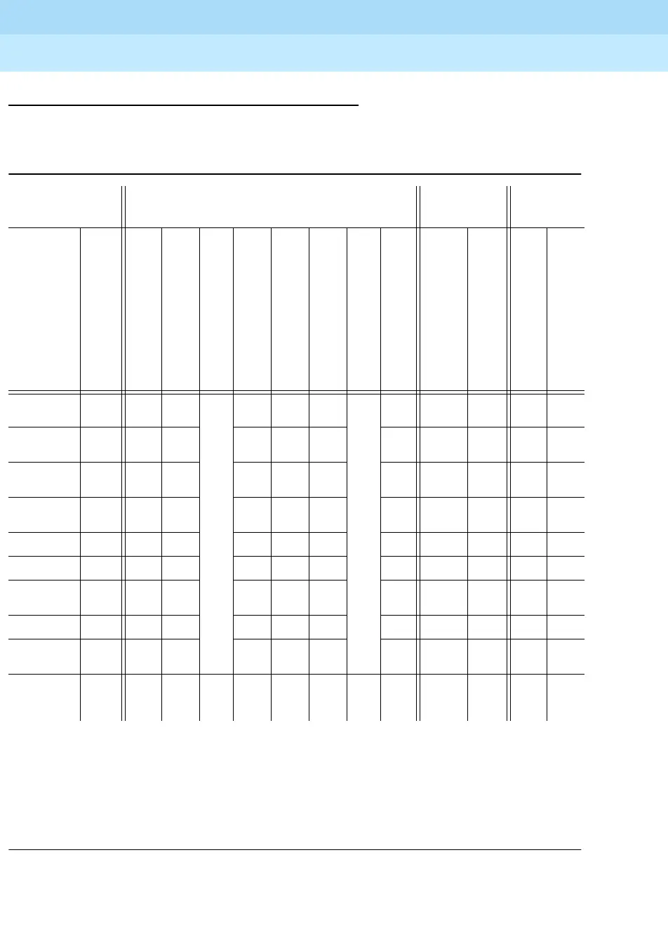
Table E-1 summarizes the TN2314 circuit pack LED states.
flash1— 800ms ON, 200ms OFF
flash2— 500ms ON, 500ms OFF
flash3— 200ms ON, 800ms OFF
flash4— 200ms OFF on every sanity heartbeat
flash5— 1 sec ON, 1 sec OFF
sw— Software Controlled
clk— Similar to the TN2182 Tone/Clock LED
Table E-1. TN2314 circuit pack LED states
Boot Sequence = 3 min., 45 sec.
Shutdown
Sequence
1-3min
Other
LED name
LED
color
Power-on reset
860 core test in progress
860 core test finished, RM initialized
PC BIOS boot
PC OS boot
Firmware download
Jump to application firmware
SPE up
Shutdown in progress
Shutdown complete
860 core test failed
Pentium BIOS update
TN2314 CP
A Alarm
red on on
Racing LEDs
on on on
Racing LEDs
sw on on on on
TN2314 Test green off on flash
1
flash
3
off sw sw off on flash
2
TN2314 In
Use
yel-
low
off off off off flash
2
flash
4
sw off on flash
2
PCMCIA yel-
low
on on sw sw sw sw sw on off on
Major Alarm red off off off off off sw sw off off off
Minor Alarm red off off off off off sw sw off off off
Clock Status yel-
low
off off off off off clk clk off off off
ETR red on on on on on sw sw on on on
OK to
Remove
green off on on off off off flash3 on on off
___________ _____ ____ (a)__
40
sec.
(b)
40
sec.
(c)
80
sec.
(d)
30
sec.
(e)