Cable Pinouts
A-1TN760E tie trunk option settings
A
Installation and Upgrades for DEFINITY ONE and
IP600 Internet Protocol Release 10
555-233-109
Issue 6
December 2001
A
Cable Pinouts
This appendix provides the following information for TN760D tie trunk and
TN464GP option settings, connector and cable diagrams, and pinout charts.
■ ‘‘TN760E tie trunk option settings’’ on page A-1
■ ‘‘TN464GP option settings’’ on page A-4
■ ‘‘Connector and cable diagrams —pinout charts’’ on page A-5
TN760E tie trunk option settings
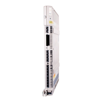
The TN760E tie trunk circuit pack interfaces between 4 tie trunks and the TDM
bus. Two tip and ring pairs form a 4-wire analog transmission line. An E and M
pair are DC signaling leads used for call setup. The E-lead receives signals from
the tie trunk and the M-lead transmits signals to the tie trunk.
To choose the preferred signaling format (Table A-1 and Table A-2 on page A-2),
set the switches on the TN760D and administer the port using Figure A-1 on page
A-2 and Table A-3 on page A-3.
Table A-1. Signaling formats for TN760E
Mode Type
E & M Type I Standard (unprotected)
E & M Type I Compatible (unprotected)
Protected Type I Compatible, Type I Standard
Simplex Type V
E & M Type V
E & M Type V Revised
 Loading...


