Electrical wiring Azbil Corporation
3-8 Model MTG11A/18A, MTG11B/18B, MTG14C
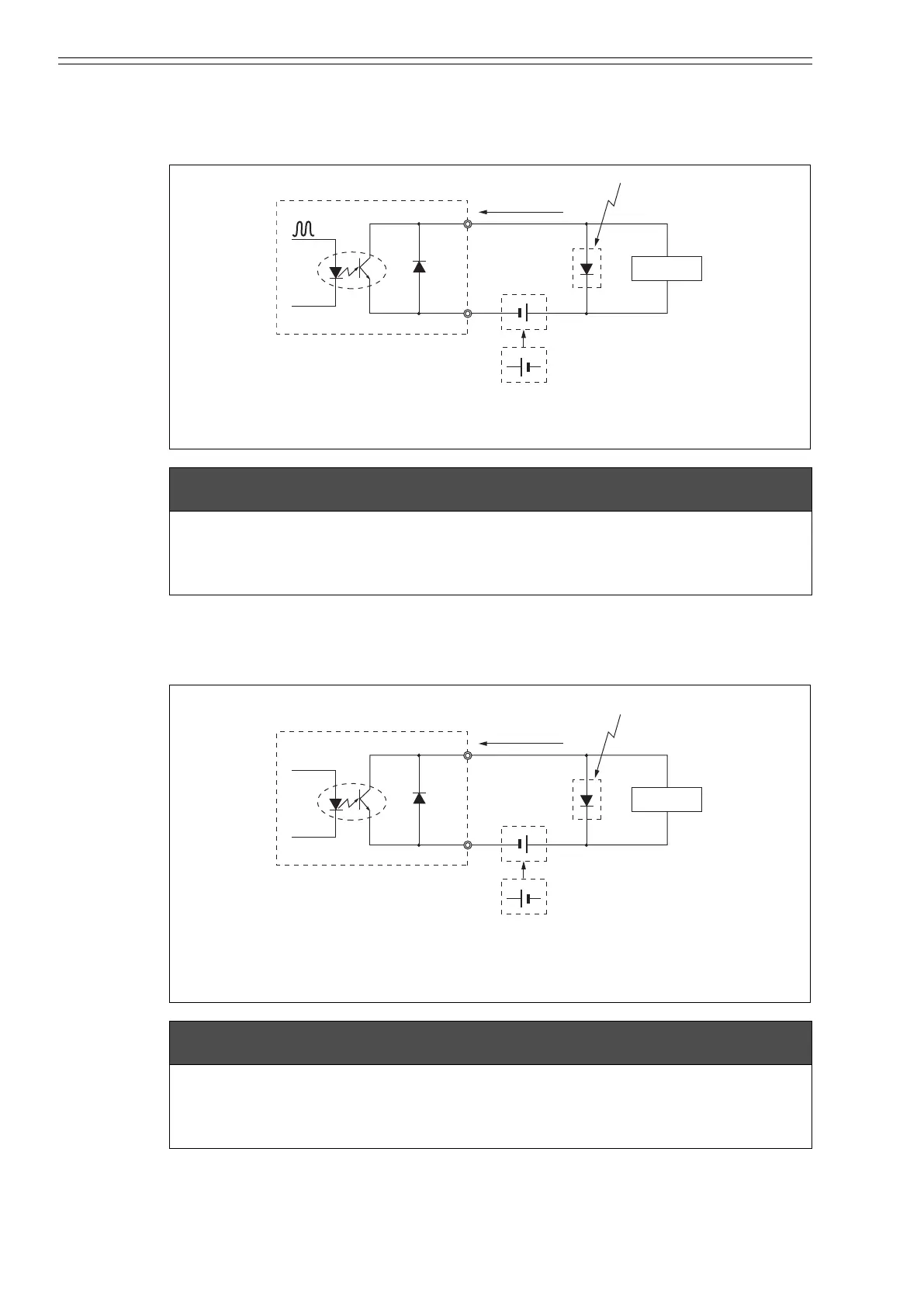
Wiring connection for pulse output
The pulse output is an open-collector output.
Carry out the wiring paying attention to the voltage and polarity.
Wiring connection for contact output
Because of an open-collector output, carry out wiring paying attention to the polarity.
Figure 3-6 Pulse output wire connection diagram
m CAUTION
• Incorrect wiring polarity can cause damage to the equipment. Double-check the
wiring position.
• Use an external power source that meets the voltage and capacity specifications.
Figure 3-7 Contact output wire connection diagram
m CAUTION
• Incorrect wiring polarity can cause damage to the equipment. Double-check the
wiring position.
• Use an external power source that meets the voltage and capacity specifications.
+–
–+
STATUS OUT +
STATUS OUT –
External power source
30 V DC max.
100mA max.
Protective diode
Load
Avoid this polarity
+–
–+
STATUS OUT +
STATUS OUT –
External power source
30 V DC max.
100mA max.
Protective diode
Load
Avoid this polarity
CM2-MTG300-2001.book 8 ページ 2015年9月29日 火曜日 午前10時14分

 Loading...