Azbil Corporation Operation using the data setting device
Model MTG11A/18A, MTG11B/18B, MTG14C 5-57
5-6-12 : Setting upper and lower limit alarm
This function is used to set the upper and lower limit alarm set points when the contact
output is selected.
An alarm is output when the flow rate exceeds these preset upper and lower limits.
The alarm output status depends on the “Setting contact output status” described later.
Set range: HI-ALM 0% to +115%
LO-ALM 0% to +115%
Default: HI-ALM +115%
LO-ALM 0%
Set the upper/lower limit alarm in accordance with the following procedure:
However, set as follows: HI-ALM > LO-ALM.
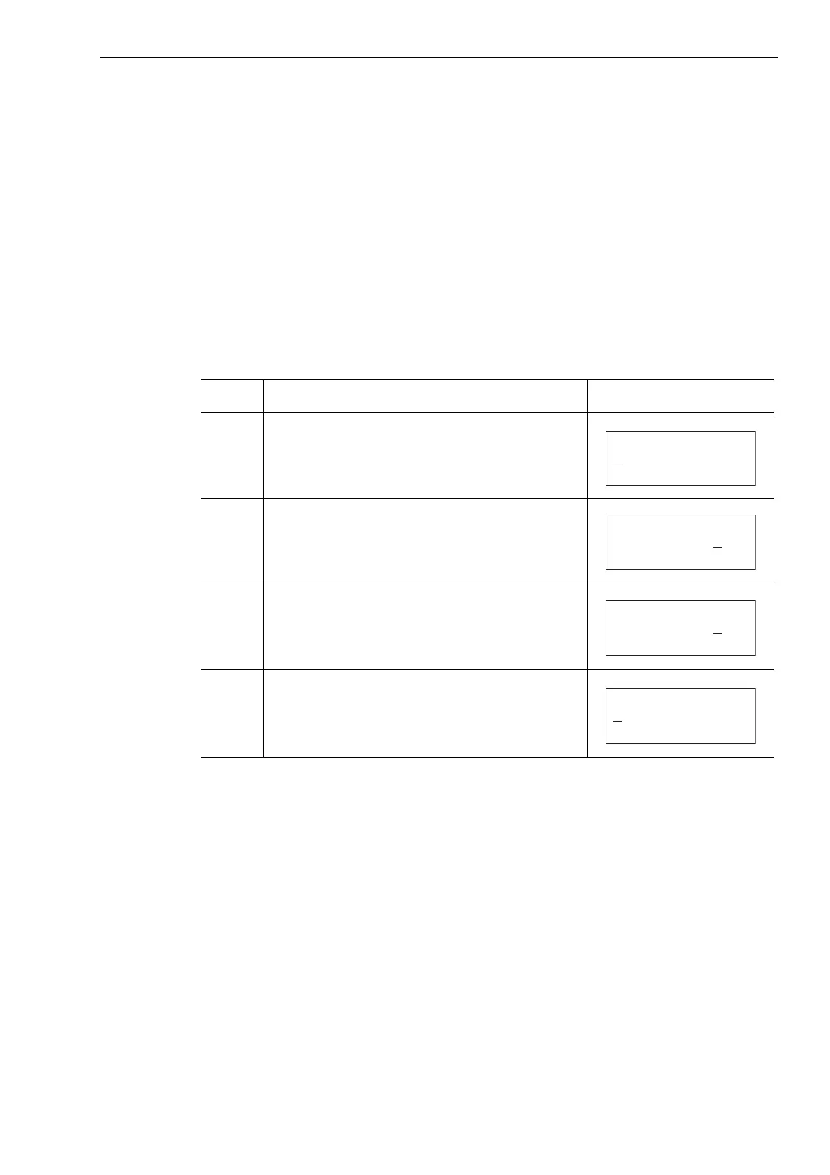
Step Procedure Screen
1 Enter ENGINEERING MODE in accordance with
the entry into ENGINEERING MODE (see
section 5-5-9 on page 5-36). Then press the or
key to display the screen at right.
2 Using the key, move the cursor to the position
under a digit to be set or changed.
3 Using the or key, change the value to the
desired value to be set.
4 Press the key to move the cursor to the position
under #.
Press MODE key to return to the MEASURING
MODE and to save data.
12.3 %
# HI-ALM +115%
LO-ALM +000%
12.3 %
# HI-ALM +100%
LO-ALM -000%
12.3 %
# HI-ALM +080%
LO-ALM -000%
12.3 %
# HI-ALM +080%
LO-ALM -000%
CM2-MTG300-2001.book 57 ページ 2015年9月29日 火曜日 午前10時14分

 Loading...