Operation using the data setting device Azbil Corporation
6-56 Model MTG11A/18A, MTG11B/18B, MTG14C
Deciding fail-safe direction: [F/S SET UP] function
Introduction
“Deciding fail-safe direction” refers to deciding the direction of output burnout if an
error causes the converter to fail to measure the flow rate. For error, refer to “Error
messages and remedial action” on page 6-32. There are three directions as shown
below.
Analog output
• Burnout up (UP) ...........Causes the readout of a signal from the converter to swing
fully in the direction of a maximum value (21.8 mA TYP).
• Burnout down (DWN)..Causes the readout of a signal from the converter to swing
fully in the direction of a minimum value (3.7 mA TYP).
• Hold (HLD) ..................Holds the output immediately to a value before the error
occurrence.
Pulse output
• Stop (STOP) .................Stops the pulse output
• Hold (HLD) ..................Keeps the output immediately to value before the error
occurrence.
Procedure
Use the following procedure to display or set the fail-safe direction of analog output.
m CAUTION
The fail-safe direction is a factor of extreme importance in securing the safety of the
entire control process. Decide the fail-safe direction considering what would be the
safer output when the output of the converter becomes abnormal in the entire
control process.
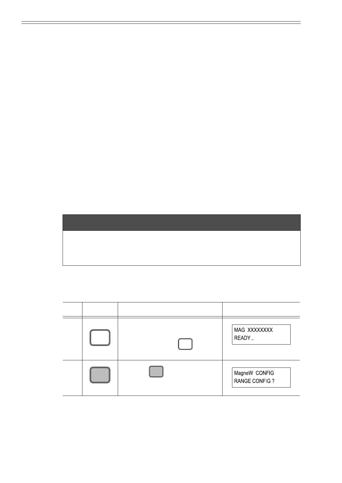
Step
Key Procedure SFC screen
1 Confirm that the SFC is set to
“READY”.
If it is not, press the key to
set it to “READY”.
2
Press the key to access the
CONFIG functions.
CM2-MTG300-2001.book 56 ページ 2015年9月29日 火曜日 午前10時14分

 Loading...