Home
Azbil
Measuring Instruments
VDC
Azbil VDC User Manual
4
of 1
of 1 rating
338 pages
Give review
Manual
Specs
To Next Page
To Next Page
To Previous Page
To Previous Page
Loading...
Azbil Corporation
Mainten
ance and troubleshooting
Model MTG11A/18A, MTG11B/18B, MTG14C
8-9
8-3 : Spar
e par
ts
8-3-1: S
p
are p
art
s for integral type
Figur
e 8-8 Spare parts for integral type
2
1
15
8, 9, 10
13
16
17
18, 18-2
11, 12
7
3
5
4
18-1
18-2
18
6
14
CM2-
MTG3
00-2
001.
book
9
ペー
ジ
2
01
5
年
9
月
2
9
日
火
曜
日
午
前
1
0
時
1
4
分
320
322
Table of Contents
Default Chapter
7
Table of Contents
7
Outline of this Chapter
17
Chapter 1 : Model MTG11A/18A/11B/18B/14C System
18
System Configuration
18
Measuring System
18
Figure 1-1 Conceptual Drawing of Measuring System (Integral Type)
18
System Configuration for Analog Output
19
Figure 1-2-1 System Configuration for Analog Output 1 (Integral Type)
19
Figure 1-2-2 System Configuration for Analog Output 1 (Remote Type)
19
System Configuration for Analog Output and Pulse Output
21
Figure 1-3-1 System Configuration for Analog Output 2 (Integral Type)
21
Figure 1-3-2 System Configuration for Analog Output (Remote Type)
21
System Configuration for Analog Output and Contact Output
22
Figure 1-4-1 System Configuration for Analog Output 1 (Integral Type)
22
Figure 1-4-2 System Configuration for Analog Output 2 (Remote Type)
22
System Configuration for Digital Output (de Output)
23
Figure 1-5-1 System Configuration for Digital Output
23
Figure 1-5-2 System Configuration for Digital Output
24
Structure of this Instrument and Functions of Its Various Parts
25
Structure of Main Unit
25
Figure 1-6-1 Overview of Integral Type
25
Figure 1-6-2 Overview of Remote Type
26
Detector 1: Flanged Type
27
Figure 1-7 Detector Details (Flanged Detector)
27
Detector 2: Wafer Type
28
Figure 1-8 Detector Details (Wafer-Type Detector)
28
Indicator/Data Setting Device
29
Figure 1-9 Indicator/Data Setting Device Details
29
Figure 1-10 Display
29
Terminal Box
30
Figure 1-11 Terminal Box Details
30
Figure 1-12-1 Terminal Block (Integral Type)
30
Figure 1-12-2 Terminal Block (Remote Type)
30
Hazardous Area Approvals and CE-Mark
32
Model MTG18A
32
Combination of FM Approval and CSA Certification for Division 1 and Division 2
32
Figure 1-13 Process Fluid Temperature and Pressure Limit for Model MTG18A
33
ATEX Type Na Certification (English)
34
Certification ATEX Type N (Français)
36
ATEX Type N Bescheinigung (Deutsch)
38
Certificación ATEX Tipo N (Español)
40
Certificazione ATEX Tipo N (Italiano)
42
ATEX Type N Certificering (Dutch)
44
Certificação de Tipo N ATEX (Português)
46
NEPSI Ex Na Certification (English)
48
MTG18B and MTG14C
51
FM Approval with Remote Models MTG18B (Detector) and MTG14C (Converter)
51
CSA Certification with Remote Models MTG18B (Detector) and MTG14C (Converter)
53
Figure 1-14 Process Fluid Temperature and Pressure Limit for Model MTG18B
53
EU Pressure Equipment Directive (97/23/EC)
54
Chapter 2 : Instrument Installation
55
Outline of this Chapter
55
Before Installation
56
Criteria for Installation Location (1)
56
Criteria for Installation Location (2)
58
Figure 2-1 Example of Installation
58
Figure 2-2 Straight Pipe Section Upstream of Detector (D: Nominal Detector Bore Diameter)
58
Figure 2-3 Maintenance Space
59
Method of Changing the Direction of Converter
60
Figure 2-4 Change the Direction of Converter
60
Changing the Direction of Display/Data Setting Device
62
Figure 2-5 Changing the Display / Data Setting Device Direction
62
Movable Range of Display/Data Setting Device
63
Figure 2-6 Movable Range of Display/Data Setting Device
63
Wiring Connection Distance of Remote-Type Converter and Detector
64
Figure 2-7 Cable Length (M) between Converter and Detector
64
Figure 2-8 Cable Length (M) between Converter and Detector
64
Installation Method
65
Installing a Wafer Type Detector
65
Basic Installation
65
Figure 2-9 Device Installation Example
65
Figure 2-10 Flange Shape
67
Figure 2-11 Examples of Unacceptable Installations (1)
68
Figure 2-12 Examples of Unacceptable Installations (2)
68
Accessory Parts for Installation
69
Figure 2-13 Horizontal Centering of the Detector
69
Figure 2-14 Vertical Centering of the Detector
69
Selecting an Installation Method
71
Installation on Horizontal Pipe
72
Installation on Vertical Pipe
73
Installation on Metal Pipe (1)
74
Figure 2-15 Installation Using SUS Material Grounding Ring and Metal Pipe
74
Installation on Metal Pipe (2)
75
Figure 2-16 Installation Using Non-SUS Material Grounding Ring and Metal Pipe
75
Figure 2-17 Example of Incorrect Installation
75
Installation on PVC Pipe (1)
76
Figure 2-18 Installation Using SUS Material Grounding Ring
76
Figure 2-19 Installation Using SUS Material Grounding Ring (with Protective Plate)
77
Figure 2-20 Installation Using SUS Material Grounding Ring (with Rubber Gasket)
77
Installation on PVC Pipe (2)
78
Figure 2-21 Installation Using Non-SUS Material Grounding Ring
78
Figure 2-22 Installation Using Non-SUS Grounding Ring (with Protective Plate)
79
Figure 2-23 Installation Using Non-SUS Grounding Ring (with Rubber Gasket)
79
Installation a Flange Type Detector
80
Basic Installation Method
80
Figure 2-24 Installation Example
80
Figure 2-25 Flange Shape
82
Figure 2-26 Example of Incorrect Mounting
82
Accessory Parts for Installation
83
Selecting an Installation Method
84
Installation on Metal Pipe (1)
85
Figure 2-27 Installation Using SUS Material Grounding Rings
85
Installation on Metal Pipe (2)
86
Figure 2-28 Installation Using Non-SUS Material Grounding Ring
86
Figure 2-29 Example of Incorrect Installation
86
Installation on PVC Pipe (1)
87
Figure 2-30 Installation Using SUS Material Grounding Ring
87
Figure 2-31 Installation Using SUS Material Grounding Ring (with Protective Plate)
88
Figure 2-32 Installation Using SUS Material Grounding Ring (with Rubber Gasket)
88
Installation on PVC Pipe (2)
89
Figure 2-33 Installation Using Non-SUS Material Grounding Ring
89
Figure 2-34 Installation Using Non-SUS Material Grounding Ring (with Protective Plate)
90
Figure 2-35 Installation Using Non-SUS Material Grounding Ring (with Rubber Gasket)
90
Installation of Remote-Type Converter
91
Figure 2-36 Wall Mounting
91
Figure 2-37 2-Inch Pipe Mounting
91
Chapter 3 : Electrical Wiring
93
Outline of this Chapter
93
Electrical Wiring
94
Figure 3-1-1 Supply Power Voltage-Load Resistance Characteristics
95
Figure 3-1-2 Terminal Block - Integral Type
95
Figure 3-1-3 Terminal Block - Remote Type
96
Figure 3-2 Grounding Procedure that Uses Internal Grounding Terminal
98
Figure 3-3 Grounding Procedure that Uses External Grounding Terminal
98
Figure 3-4 Wire Connection Diagram
99
Figure 3-5 Wire Connection Diagram (When Inputting to the Sequence Controller Etc.)
99
Figure 3-6 Pulse Output Wire Connection Diagram
100
Figure 3-7 Contact Output Wire Connection Diagram
100
Figure 3-8 Wiring for Power Supply - Integral Type
102
Figure 3-9 Wiring for Power Supply - Remote Type
102
Figure 3-10 Wiring Connection between Detector and Converter
102
Chapter 4 : Operation
103
Outline of this Chapter
103
Confirmation before Start-Up
104
Stopping
105
Chapter 5 : Operation Using the Data Setting Device
107
Startup
108
Display and Operation Contents of Data Setting Device
109
Functions of the Data Setting Device
111
Data Setting Device
111
Description of MEASURING MODE
113
Display Overview
113
Display of Write Protect Level
114
Overview of Operation Using the Data Setting Device
116
Configuration of OPERATOR'S MODE
117
Changing Setting of Damping Time Constant
120
Figure 5-1 Damping Output Characteristics
120
Auto Zero Adjustment
121
Setting of Built-In Counter Reset Value
122
Setting of Built-In Counter Reset Value
123
Setting Auto Spike Cut
124
Figure 5-2 Auto Spike Cut Output Characteristics
124
Setting Moving Average Processing
125
Figure 5-3 Output Characteristics of Moving Average Processing
125
Setting Electrode Status Diagnostic Function
127
Electrode Status Diagnostic Troubleshooting
136
Selecting the Electrode Status Output Mode
137
Selecting Flow Rate to be Displayed in the Main Display
139
Selecting a Communication System
140
Entering ENGINEERING MODE and MAINTENANCE MODE
142
Configuration of ENGINEERING MODE
144
Setting ID
147
Setting Detector Information
150
Setting Detector Factor
151
Setting Flow Rate Range
152
Setting and Changing Compensation Coefficient
153
Setting Specific Gravity
154
Setting Pulse Scale
155
Setting Pulse Width
157
Setting Drop out
160
Setting Low Flow Cutoff
162
Setting Upper and Lower Limit Alarm
163
Selecting Failsafe Mode for Analog Outputs
164
Selecting Failsafe Mode for Pulse Output
165
Setting Contact Output Status
166
Configuration of MAINTENANCE MODE
167
Configuration of OUTPUT CHECK MODE
168
Performing Loop Checks of Analog Outputs
171
Performing Loop Checks of Pulse Outputs
172
Performing Loop Checks of Contact Outputs
173
Configuration of CALIBRATION MODE
174
Manual Zero
178
Configuration of CRITICAL MODE
180
Displaying ROM Version and Date
181
Returning to Settings at Shipment
182
Description of Error Messages
183
Chapter 6 : Operation Using SFC Communicator
185
Structure and Functions of SFC
185
6-1-1: Structure of SFC
185
Structure of Smart Field Communicator (SFC)
185
Figure 6-1 Details of SFC
185
6-1-2: Functions of SFC
187
SFC Keyboard
187
Rules of Key Operations and Interaction with Screens
188
Charging SFC
194
6-1-3: SFC Wiring
195
Wiring between Two Wired Magnetic Flowmeter Converter and SFC
195
6-1-4: SFC Unavailable Functions
195
Figure 6-3 SFC Wiring Connection
195
6-1-5: before Operating SFC
196
Status of Two Wired Magnetic Flowmeter SFC at SFC Communication
196
Confirm Write Protect Mode
196
Writing on Non-Volatile Memory
197
Changing Communication Method
197
Figure 6-4 Data Setting Screen
197
Configuration Using SFC Communicator
198
6-2-1: before Communicating Using the SFC
199
What Can be Done Using the SFC
199
Hierarchical Structure of CONFIG Functions
201
SFC Hierarchical Structure Chart
201
Example of a Key Sequence
202
Starting Communication: ID/DE READ Key
203
Entering TAG No.: ID Key
205
Setting/Changing Damping Time Constant: DAMP Key
207
Setting Engineering Units: UNITS Key
208
Setting Output Range and Correction Coefficient: URV Key
210
Displaying Transmitting Output: OUTPUT Key
211
Loop Check of Output Signal
212
Making Zero Adjustment: CORRECT Key
213
Displaying Flow Rate Measured Value: INPUT Key
214
Displaying Self-Diagnostics Result: STAT Key
215
Error Messages and Remedial Action
216
Displaying Software Version: SW VER Key
219
Data Printing
220
Printing Internal Data: PRINT Key
221
Continuously Printing Response Result: ACT PRINT Key
223
6-2-3: Setting Using SFC Communication (2) - Setting Using CONFIG Functions
226
Selecting Unit System and Setting Specific Gravity [UNIT KEY] Function
226
Setting or Changing Low Flow Cutoff: [CUT-OFF] Function
228
Changing Flow Rate Display: [DISP] Function
230
Setting Detector Constant: [EX(Ma)] Function
232
Setting Detector Type: [TYPE] Function
234
Setting Diameter of Detector: [DIAMETER=] Function
236
Setting High/Low Alarm Values [ALARM CONFIG] Function
238
Deciding Fail-Safe Direction: [F/S SET UP] Function
240
Setting Burnout Direction of Pulse Output: [F/S SETUP] Function
242
Select Pulse Output / Contact Output [DIGITAL I/O] Function
244
Setting Contact Output Status [DIGITAL I/O] Function
246
Checking Output of Contact Output: [DI/DO CHECK] Function
248
Adjusting Analog Current Output [CORRECT DAC] Function
250
Calibrating Gain Constant [GAIN CAL] Function
252
Resetting the Internal Data to Factory Setting (Default) [SHIP DATA RECOV] Function
254
Displaying Totalized Value [READ TOTAL] Function
255
Checking Pulse Output [PULSE OUTPUT] Function
256
Setting Pulse Scale and Pulse Scale Unit [PULSE CONFIGURE] Function
258
Setting Pulse Width [PULSE CONFIGURE] Function
260
Setting Dropout [PULSE CONFIGURE] Function
262
Setting Counter Reset Function [RESET TOTALZE] Function
264
Chapter 7 : Operation Using HART Communicator
267
Preparation for Communication, Verification and Cautions on Use
267
Wiring between Converter and HART Communicator
267
Two Wired Magflow Meter Converter Setting
268
Verifying Communication
270
Cautions
270
Setting and Calibrating Devices Using the HART Communicator
271
Setting Procedures
272
Flow Units
272
Range
273
Specific Gravity
273
Damping Time Constant
274
Zero Adjustment
275
Selecting Display
276
Selecting Function
276
Correction Coefficient Setting
277
Changing Communication Method
278
Setting Converter Data
279
Detector Diameter
279
Detector Type
279
Detector Constant
280
Signal Processing
281
Auto Spike Cut
281
Setting Average Processing
281
Setting the Average Processing Time
282
Low Flow Cutoff
282
Drop-Out
283
Electrode Status Sensitivity
283
Electrode Status Output Mode
284
Pulse Setting
285
Pulse Scale Unit
285
Pulse Scale
285
Pulse Width
286
Totalized Value Setting
287
Displaying Totalized Value
287
Integrated Reset Value
287
Resetting the Totalized Value
288
Contact Output Setting
289
High Alarm Value Setting
289
Low Alarm Value Setting
290
Contact Output Status Setting
290
Burnout Setting
291
Analog Output Burnout Setting
291
Pulse Output Burnout Setting
291
Calibrating and Inspecting the Device by HART Communicator and Other Functions
292
Device Adjustment
292
Analog Current Output Adjustment
292
Manual Zero
294
Gain Adjustment
296
Pulse Output Adjustment
298
Excitation Current Adjustment
300
Output Check
302
Analog Output Check with MGZ Calibrator
302
Analog Output Check
303
Pulse Output Check
304
Contact Output Check
305
Other Functions
306
Verifying Status of Converter
306
Tag Setting
307
Shipping Data Recovery
308
Review
309
Short Cut Commands and Menus for HART Communicator
310
Short Cut Keys
310
Menu Tree
311
Chapter 8 : Maintenance and Troubleshooting
313
Outline of this Chapter
313
Maintenance and Inspection of Parts
314
8-1-1: Replacement of Indicator / Data Setting Device
314
Figure 8-1 Replacement of Indicator/Data Setting Device (with the Cover Removed)
314
Troubleshooting
318
Types of Troubles
318
Troubles at Startup
319
Troubles During Operation
320
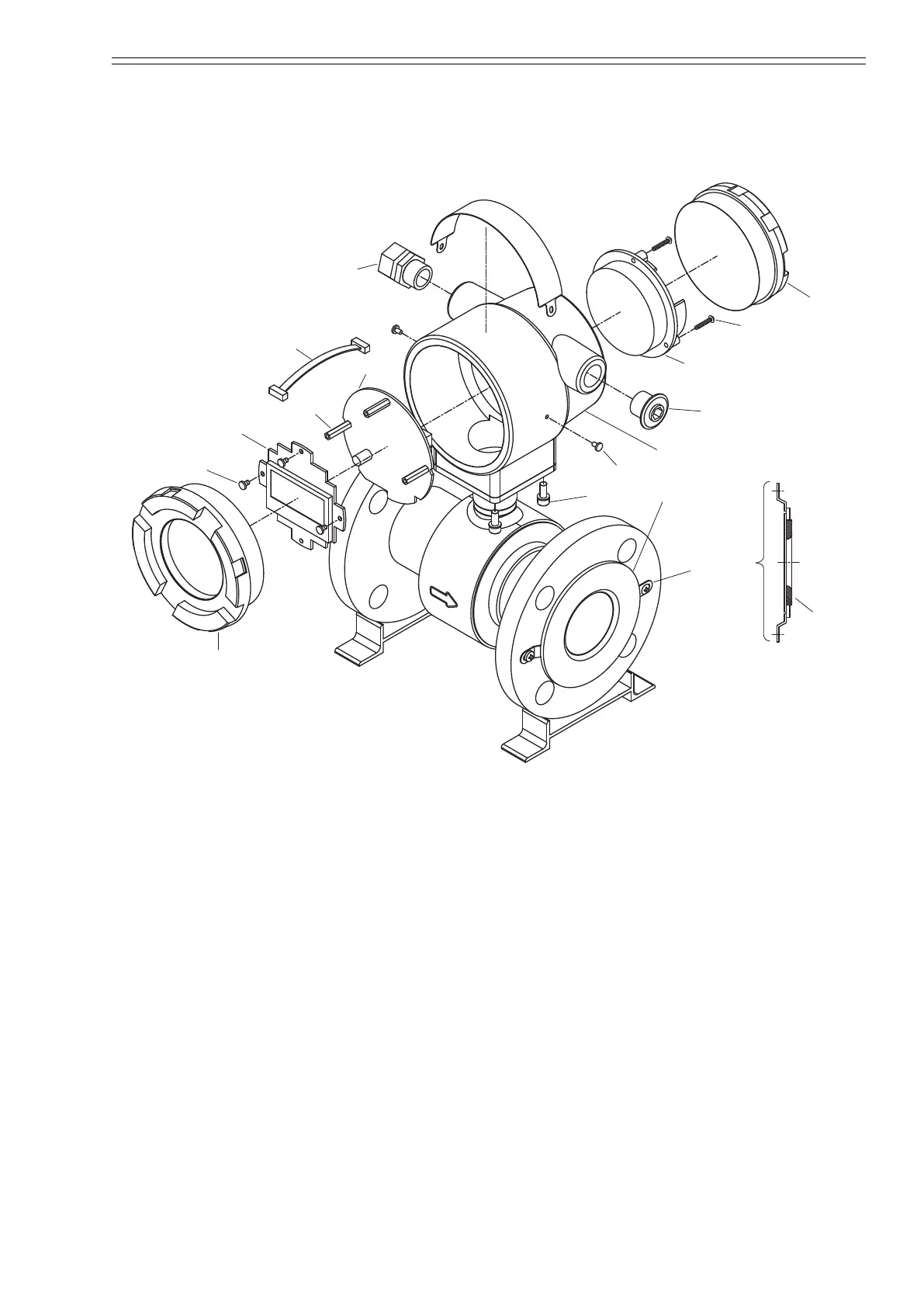
Spare Parts
321
8-3-1: Spare Parts for Integral Type
321
Figure 8-8 Spare Parts for Integral Type
321
8-3-2: Spare Parts for Remote Type Converter
323
Figure 8-9 Spare Parts for Remote Type Converter
323
8-3-3: Spare Parts for Remote Type Detector
325
Figure 8-10 Spare Parts for Remote Type Detector
325
4
Based on 1 rating
Ask a question
Give review
Questions and Answers:
Need help?
Do you have a question about the Azbil VDC and is the answer not in the manual?
Ask a question
Azbil VDC Specifications
General
Brand
Azbil
Model
VDC
Category
Measuring Instruments
Language
English
Related product manuals
Azbil MagneW 3000
20 pages
Azbil AUR355
60 pages
Azbil MCF0250
56 pages
Azbil MCF0080
56 pages
Azbil MagneW Neo PLUS
338 pages

 Loading...