Model MTG11A/18A, MTG11B/18B, MTG14C 7-1
Chapter 7 : Operation using HART
communicator
7-1 : Preparation for communication, verification
and cautions on use
This section describes the preparation necessary for communication between a device
and a HART Communicator. This section also covers the procedure to verify
communication. The first step for preparation is to perform wiring between the
converter and the HART Communicator. After wiring has been completed, turn the
power on and verify that communications are functioning properly.
7-1-1 : Wiring between converter and HART Communicator
The following describes the methods of wiring between converter and HART
Communicator.
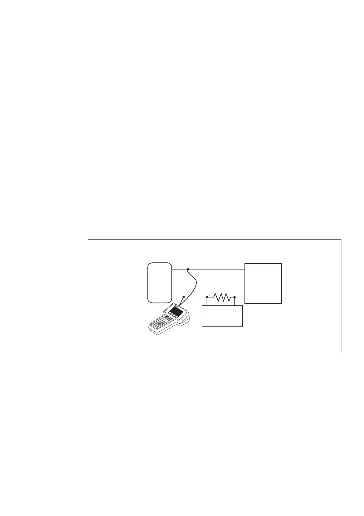
Connect the HART Communicator as shown in Figure 7-1. A 250Ω resistor must be
installed on the receiving end of the output current. There is no polarity on the HART
Communicator terminal.
Figure 7-1 HART Communicator wiring
24V DC
7
A
B
C
8
HART Communi
cator
9
G
H
I
4
J
K
L
5
M
N
O
6
P
Q
R
1
S
T
U
2
V
W
X
3
Y
Z
/
0
#
%
&
.
<
>
_
*
:
+
D
E
F
O
I
F
I
E
L
D
C
O
M
M
U
N
I
C
A
T
IO
N
S
P
R
O
T
O
C
O
L
F4
F
3
F1
F
2
MTG
Converter
I.OUT +
I.OUT -
HART communicator
250 Ω
Host control
system
+
-
CM2-MTG300-2001.book 1 ページ 2015年9月29日 火曜日 午前10時14分

 Loading...