Azbil Corporation Operation using the data setting device
Model MTG11A/18A, MTG11B/18B, MTG14C 5-39
~Note After the MODE key is pressed, configured data in the
ENGINEERING MODE are saved in non-volatile memory. When
configure data, be sure to press the MODE key to save the data.
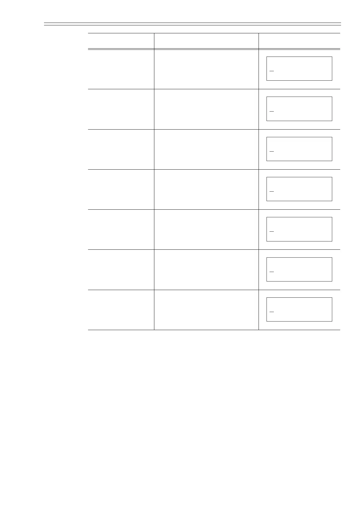
PLS WID Sets the output pulse width.
DROP OUT Sets drop out.
LOW FLOW CUT Sets low flow cut.
HI-ALM/LOW-ALM
Sets upper/lower limit alarm.
ERROR OUT MODE
I. OUT
Determines the analog output
failsafe direction.
ERROR OUT MODE
P. OUT
Determines the pulse output failsafe
direction.
ST. OUT MODE Sets a contact output status.
Item Contents Screen
20.0 %
# PLS
0010 ms
10.000 Hz
WID
20.0 %
# DROPOUT
10 %
20.0 %
# LOW FLOW CUT
10 %
20.0 %
# HI-AIM
LO-AIM
0 %
100 %
20.0 %
# ERROR OUT MODE
I.OUT HOLD
20.0 %
# ERROR OUT MODE
P.OUT HOLD
20.0 %
# ST. OUTMODE
NORMAL CLOSE
CM2-MTG300-2001.book 39 ページ 2015年9月29日 火曜日 午前10時14分

 Loading...