190 CONFIGURA TION
13.8.1.3 Connecting to multi-state logic parameters
When connecting to multi state logic parameters (E.g. SPEED FBK TYPE or UIPX RA NGE), the states are
placed in numerical order as follo ws.
1
st
choice = logic 0
2
nd
choice = logic 1
3
rd
choice = value of pure number 2
4
th
choice = value of pure number 3
5
th
choice = value of pure number 4
Hence in order to switch betw een choice 1 (value 0) and 2 (value 1) a normal logic flag may be connected as
the source of control. If the block providing the instuction to change state, possesses a value for high/low
output, (e. g. digital input DIP1) ensure that a lo w is 0.00% value, and a high 0.01% value.
To switch bet w een type 4(value 3) and type 5(value 4), use a value for low of 0.03%, and for high, 0.04%.
If the source of logic state is internal and does not possess a value for high/low, then utilise one of the C/O
SWIT CHES. See the Applications Manual for details of the C/O SWITCH.
E. g. The C/O SWIT CH uses a logic value to switch bet ween a HI value input and a LO value input.
To switch bet w een type 4(value 3) and type 5(value 4), use a LO value of 0.03%, and HI value, 0.04%.
Hence w hen the logic value is 0, the C/O SWITCH will send the value of pure number 3 to the multi state
PIN, and then choice 4 will be selected. Like wise choice 5 will be selected for a logic 1.
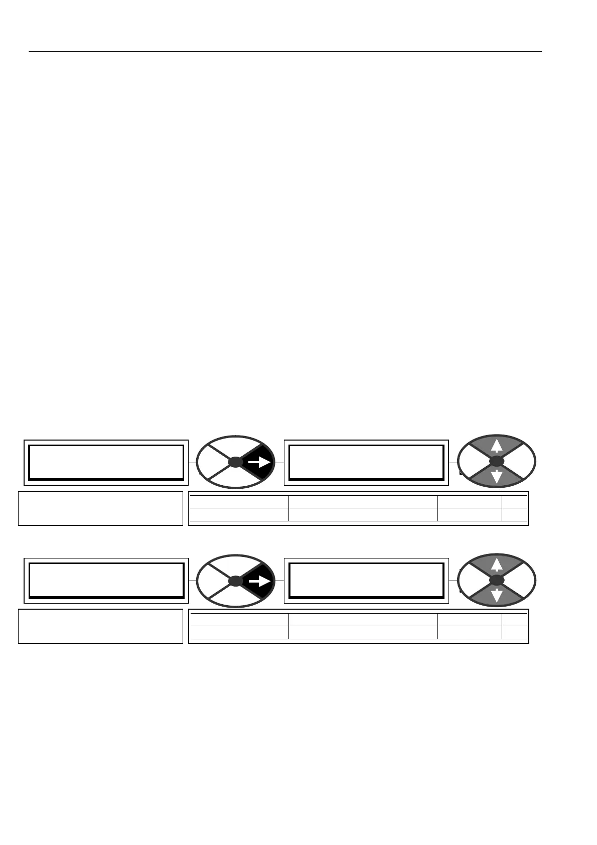
13.8.2 ST A GING POSTS / Digital / analog 1/2/3/4 PINs 2 96 to 303
When a pure logic value of 0 arrives at a DIGIT AL SOFT W ARE POST the display will sho w LO W. When a
pure logic value of 1 arrives it will sho w HIGH.
ST A GING POSTS 3
296)DIGIT AL POST 1
296)DIGIT AL POST 1
LO W
PARA METER RA NGE DEFAULT PIN
DIGIT AL POST 1 HIGH or LOW LOW 296
Used as storage point for logic
state and/or connecting point.
ST A GING POSTS 3
300)ANALO G POST 1
300)ANALO G POST 1
0.00%
PARA METER RA NGE DEFAULT PIN
ANALO G POST 1 + /-300.00 % 0.00 % 300
Used as storage point for linear
values and/or connecting point.