204 Installation
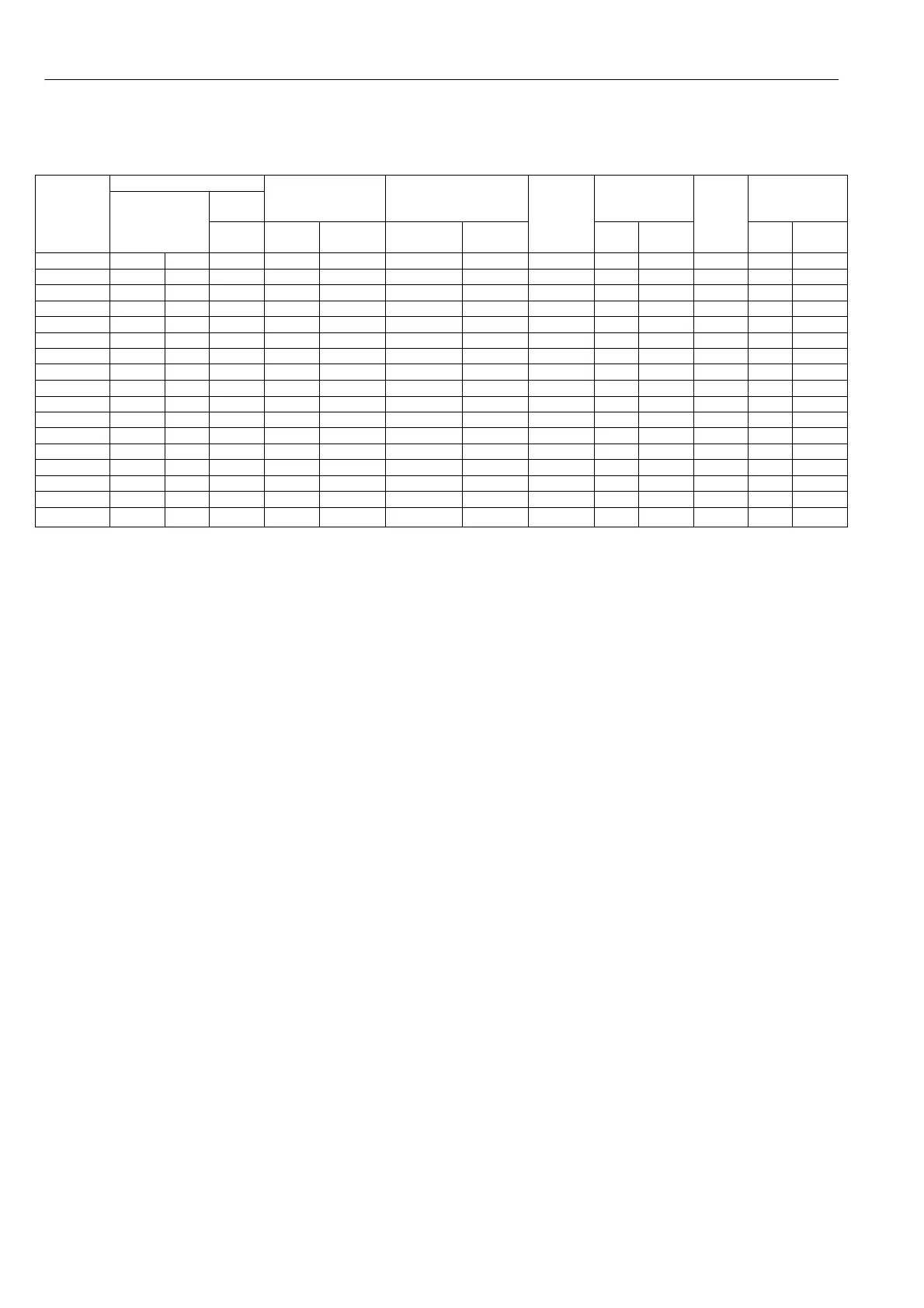
14.1 Product rating table
Output power
At
500 V
Max continuous
Current (AMPS)
Maximum field
output current
(DC Amps)
Maximum
Auxiliary
Fuse ratings
Cooling air
flo w and
dissipation
Model
PL 2Q
PLX 4Q
At
4 60V
K w HP
HP
Input
A C
Output
DC
Standard Option
Main
fuses
max
I
2
t
Amp I
2
t
Line
reac
-tor
type
cfm w atts
PL/X 5 5 7 7.5 10 12 8 600 20 365 LR48 17 45
PL/X 10 10 1 3 15 20 24 8 600 2 0 365 LR48 17 80
PL/X 15 15 2 0 20 30 36 8 600 2 0 365 LR48 17 120
PL/X 20 20 2 7 30 40 51 8 5000 20 365 LR48 1 7 120
PL/X 30 30 4 0 40 60 72 8 5000 20 365 LR120 35 200
PL/X 40 40 5 3 60 80 99 8 5000 20 365 LR120 35 300
PL/X 50 50 6 7 75 100 123 8 1 1850 20 365 LR1 20 35 320
PL/X 65 65 9 0 100 1 24 155 16 6 0000 20 365 LR270 60 350
PL/X 85 85 1 15 125 164 205 16 60000 20 365 LR270 60 475
PL/X 115 115 1 55 160 216 2 70 16 128000 20 365 LR270 60 650
PL/X 145 145 1 90 200 270 3 30 16 128000 20 365 LR330 60 850
PL/X 185 185 2 50 270 350 4 30 32 50 240 000 50 5000 LR4 30 180 1 000
PL/X 225 225 3 00 330 435 5 30 32 50 240 000 50 5000 LR5 30 180 1 300
PL 2 65 265 360 400 520 630 32 50 306000 50 5000 LR630 180 160 0
Plea se also refer to Part 3 PL/X 275-980 for extra details of frame 4 and 5 high power dri ves.
Notes
1) Only use UL fuses for installations complying with UL codes.
2) 2Q models PL/5/10/15/20/30/40/50/1 45/2 25 have a regenerative stopping capability.
3) The PL/X 185/225/26 5 requires 3 auxiliary fuses, (max ratings 50A, I
2
t 5 000), standard type CH00850 A.
4) The standard auxiliary fuses in the above table are chosen for the I
2
t rating. When selecting alternative
types the fuse current rating must be at least 1.25 X the field current rating of the motor. The I
2
t rating of
the fuse must not exceed the figure in the table.
5) Please consider the total component dissipation within the enclosure when calculating the required air
throughput. This includes the fuses, line reactors and other sources of dissipation. See 14.8 Line reactor and
14.3 Semiconductor fuse ratings for component dissipation ratings.
6) 35 Cubic feet per minute is approximately equivalent to 1 cubic metre per minute.
180 Cubic feet per minute is approximately equivalent to 6 cubic metres per minute.
7) The output pow er rating sho wn is at the 100 % rating of the drive and is the pow er available at the shaft
for a typical motor. The actual po w er available will depend on the efficiency of the motor.
8) The high po w er field output option is an extra cost facility and needs to be specified at the time of order.
14.2 Product rating labe ls
The product rating labels are located on the unit under the upper end cap. The product serial number is
unique and can be used by the manufacturer to identify all ratings of the unit. The pow er ratings and model
type are also found here, along with any product standard labels applicable to the unit.
14.3 Semiconductor fuse ratings
WARNING. All units must be protected by cor rectly rated semi-conductor fuses. Failure to do so will
invalidate warranty.
In general the input A C supply current per phase is 0.8 times the DC output current, and the fuse rating
should be approx. 1.25 times the input AC current. The fuses specified in this table have been rated to
include the 150% overload capability and operate up to 5 0C ambient at the maximum drive rating. To select
a fuse at other ratings (E.g. w hen using a motor rated at a lo wer power than the drive unit or operating at a
reduced maximum current limit setting) select a fuse with a current rating closest to the armature current and
with an I
2
t rating less than the maximum sho wn in the table. If a D C fuse is fitted in series with the armature
it must be a DC rated semiconductor type with current rating 1.2 times the motor full load current, D C
voltage rating suitable for the maximum armature voltage and with an I
2
t rating less than the maximum
sho wn in the table. See 14.3.3 D C semi-conductor fuses.