CHA NGE PARA METERS 85
CH A NGE PARA METERS 2
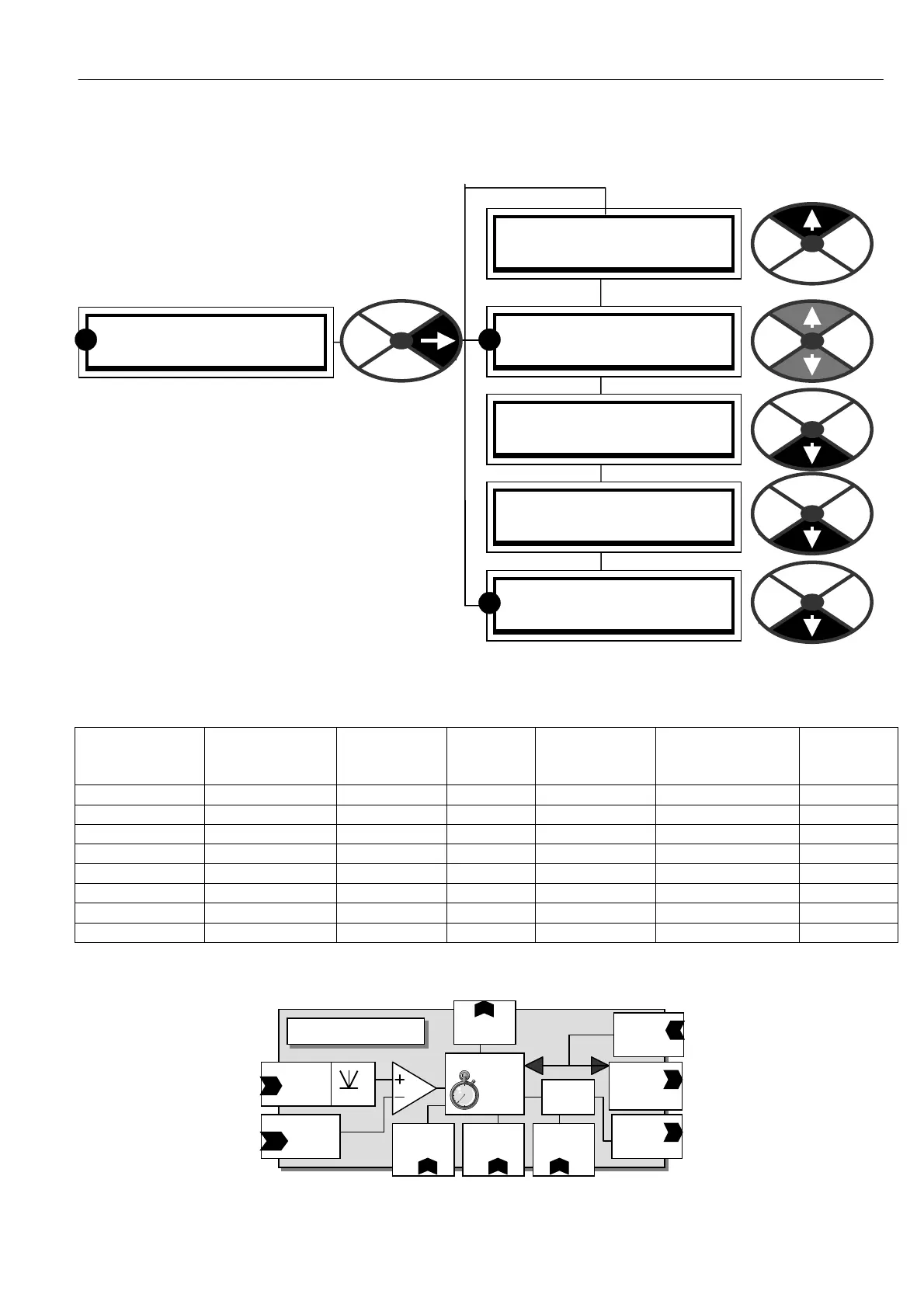
STOP MODE RAMP 3
STOP MODE RAMP 3
60)DROP-OUT DELAY
STOP MODE RAMP 3
56)ST OP RA MP TIME
STOP MODE RAMP 3
57)ST OP TIME LIMIT
STOP MODE RAMP 3
58)LIVE DELA Y MODE
STOP MODE RAMP 3
59)DROP-OUT SPEED
RR
R
6.5 CHANGE PARAMETERS / STOP MODE RAMP
PIN numbers range 56 to 60
This menu allows setting of the contactor drop
out behaviour.
See 6.7.1 SPEED CONTROL / Block diagram.
6.5.1 ST OP M ODE RA MP / Block diagram
Operating
function
JO G MO DE
SELECT T19
IP level
ST ART T3 3
IP level
JOG T32
IP level
Ramp input
Total value
Applied ramp
time
Contactor
state
Stopped low lo w low reference Stop ramp OFF
Stopped high lo w lo w reference Stop ramp OFF
Running low high low reference Run mode ramp ON
Slack 1 takeup low high high ref + slack 1 Jog/slack ramp ON
Slack 2 takeup high high high ref + slack 2 Jog/slack ramp ON
Jog speed 1 lo w low high Jog speed 1 Jog/slack ramp ON
Jog speed 2 high lo w high Jog speed 2 Jog/slack ramp ON
Crawl high high low Crawl speed Run mode ramp ON
This table sho ws when the STOP MO DE RA MP is applied.
ST OP M ODE RA MP
PIN 131
Speed
Feedback
Rect
PIN 58
Live delay
mode
PIN 60
Drop out
Delay
PIN 57
Stop time
limit
PIN 59
Drop out
Speed
Contactor drop
O ut
TIMER
Control
logic
Contactor
Control
Enable
Control
logic
Internal
enable
Stop mode
Ramp time.
To speed
control block
Stop mode
Ramp time
PIN 56