BlackTrax Zones
Three-dimensional areas called Zones, can be drawn inside the virtual representation of the Space
in BTWYSIWYG. Zones are an incorporeal volume and can only be viewed in BTWYSIWYG, but if created,
exists simultaneously in the virtual and physical Space. Zones are available in rectangular, cylindrical
and spherical shapes of any size.
BlackTrax has a number of preset interaction between Zones and fixtures, which can be accessed in the
Chapter section in BlackTrax. For more information see To enable a Zone for a Fixture.
To draw a rectangular zone
In BTWYSIWYG CAD mode, click the Wireframe view tab.1.
From the BlackTrax menu, choose BT Zone and then choose Rectangular Zone.2.
Result: The New Rectangular Zone window appears.
In the New Rectangular Zone window, in the Width field, enter in the width of the Zone.3.
In the Depth field, enter in the depth of the Zone.4.
In the Height field, enter in the depth of the Zone.5.
Note: Alternately, Zone dimensions can be created by selecting Interactive. The Zone is then
drawn in Wireframe view, and dimensions are automatically recorded.
In the Zone Name field, enter a unique name for the Zone.6.
Click OK.7.
Result: The Zone will be inserted into the Space. It can be repositioned by dragging and
dropping where needed. The dimensions of the Zone can be altered by manipulating the
Zone directly, or by right-clicking the Zone and selecting Properties.
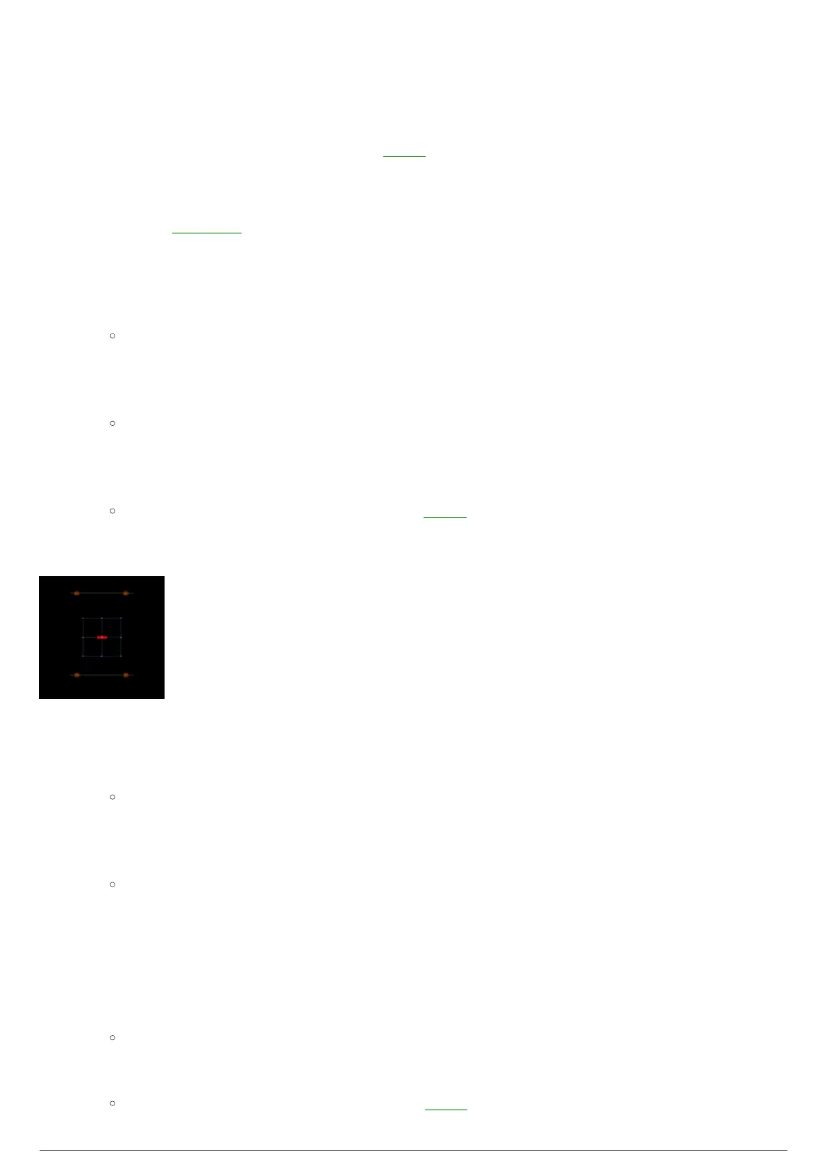
BTWYG drawing with a Rectangular Zone selected
To draw a cylindrical zone
In BTWYSIWYG CAD mode, click the Wireframe view tab.1.
From the BlackTrax menu, choose BT Zone and then choose Cylindrical Zone.2.
Result: The New Cylindrical Zone window appears.
In the New Cylindrical Zone window, in the Height field, enter the height of the Zone.3.
In the Horizontal Radius field, enter in the horizontal radius of the Zone.4.
In the Vertical Radius field, enter in the vertical radius of the Zone.5.
Note: Alternately, Zone dimensions can be created by selecting Interactive. The Zone is then
drawn in Wireframe view, and dimensions are automatically recorded.
Lock Ratio controls the aspect ratio of the radius. This feature is enabled by default. To disable,6.
clear the Lock Ratio checkbox.
Number of Segments controls how many segments make up the radius of the cylindrical Zone. The7.
default is set to 16. To change the number of segments, clear the Use Document Defaults
checkbox. Enter the new segment number in the field.
Note: The maximum number of segments allowed is 40.
In the Zone Name field, enter a unique name for the Zone.8.
Click OK.9.
Result: The Zone will be inserted into the Space. It can be repositioned by dragging and